55
Diagram 15.8
13003
15 Replacement of Parts
Diagram 15.9
13003
Diagram 15.10
13004
15.15 Casing Seal
Refer to Section 13.8.
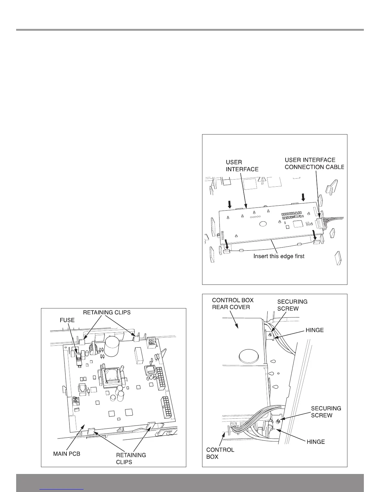
15.16 Access to User interface and Main PCB
For access, refer to section 15.1.
Hinge down the control box and unclip the rear cover to gain
access.
Remove electrical connections from main PCB noting their
positions for replacement.
Unclip main PCB and remove, see diagram 15.8.
Unclip user interface and remove.
For replacement, see diagram 15.9 and ensure that the user
interface connection cable is retted.
NOTE: When re-tting any of the control boards make sure
you support the control box to avoid straining hinges as you
push down and clip back into place.
15.17 Control Box
For access, refer to section 15.1.
Hinge down the control box and unclip the rear cover to gain
access.
Remove relevant electrical connections from main PCB and
grommets from the control box.
MPORTANT: Support the control box whilst undoing the
hinges.
Remove the hinge securing screws accessed from beneath
the boiler and remove the control box, see diagram 15.10.
15.18 Fuse - Main PCB - Control Box
For access, refer to section 15.16.
The fuse is located at the top left hand corner of the main
PCB, see diagram 15.8.
15.19 Installer Interface Electrical Cartridge
Remove the Installer Interface securing screw accessed from
beneath the boiler.
Carefully pull down the electrical cartridge, disconnect the
cables.

 Loading...


