Supplied By www.heating spares.co Tel. 0161 620 6677
27
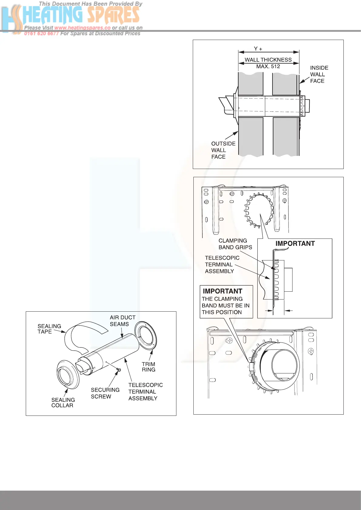
9 Flue Preparation and Installation
9.15 Rear flue - Telescopic Part No.
A2043500. Refer to diagram 9.14 for kit
contents.
9.16 Flue Length
Measure the distance from the outside wall to the inside
wall face. This measurement must not exceed 512mm. if the
dimension is less than 291mm DO NOT cut the flue, it can
project to its maximum.
9.17 Flue Fitting
Set the flue to the required length ‘Y’ plus 24mm MIN to
28mm MAX, see diagram 9.16, ensure the air duct seams line
up. Mark the securing hole position in the air duct. Drill a 3mm
diameter hole at this position, take care not to pierce the
inner flue duct. Secure with screw provided and tape the joint,
see diagrams 9.14 and 9.15.
Fit
the sealing collar onto the locating ring on
the flue terminal,
see diagram 9.6.
Push the telescopic terminal assembly into the wall, externally
or internally
, initially.
Draw the telescopic flue through the wall and engage the
telescopic terminal assembly into the clamping band grips.
The telescopic terminal assembly must be pulled forward of
the clamping band grips by the dimension shown in diagram
9.16 to ensure a good seal when the boiler is located onto the
fixing plate.
Ensuring the correct alignment of the terminal.
Secure the telescopic terminal assembly using the clamping
band supplied.
The position of the clamping band securing
screw is important, refer to label and wall template.
IMPORTANT
: CHECK THE CLAMPING BAND IS
SUFFICIENTLY
TIGHTENED TO AVOID ANY MOVEMENT
OF THE FLUE WHEN FITTING THE BOILER.
Remove the rear flue outlet cover secured with four screws.
Fix the boiler to the wall, refer to Section 6 Boiler Fixing.
Diagram 9.15
12966
Diagram 9.16
12958
13203
Diagram 9.14

 Loading...


