Supplied By www.heating spares.co Tel. 0161 620 6677
9 Flue Preparation and Installation
9.18 Vertical flue
The vertical flue system is available as an option where the
boiler position does not permit the use of the top horizontal or
rear flue system.
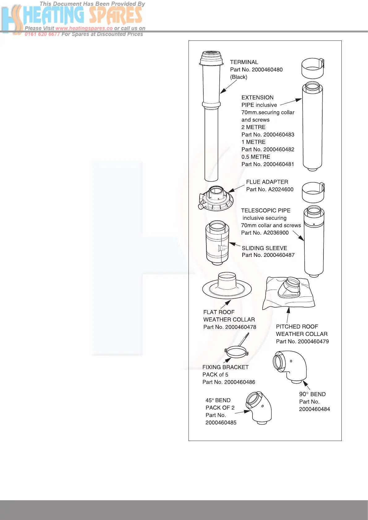
The system is made up of accessories. The accessories
include terminal assembly, bends 45º and 90º, flue
extensions, fixing bracket and appropriate weather collar, see
diagram 9.17.
The maximum permitted straight flue length is 8 metres plus
the terminal. for each 90
o
or 2x45
o
bends fitted, the maximum
length must be reduced by 1 metre, see diagram 9.22.
NOTE: 2x45º bends can replace 1x90º bend if necessary.
When using 90º bends any horizontal extension pipe should
be inclined by a minimum of 44mm/metre (2.5°) towards the
boiler to facilitate condense removal, see (a) in diagram 9.22.
Alternatively use 45º bends to avoid horizontal runs, see (b) in
diagram 9.22.
The terminal should be positioned at least 600mm from any
opening into the building, refer to diagram 3.2.
Measure the distance of fl
ue length required for the
installation.
The flue must be designed with a continuous fall towards the
boiler.
Remove the top flue outlet cover secured with four screws,
see diagram 9.2.
Refer to diagram 9.18. Secure the fl
ue adapter in position
on top of the boiler with four torx headed screws supplied,
making sure the nib fits into the locating slot in the boiler
casing to ensure correct orientation.
The rubber ‘O’ rings of each section should be lubricated prior
to assembly.
NOTE: Do not use mineral oils or grease, silicon grease or
water is recommended.
Secure the first extension pipe to the flue adapter with the
securing collar supplied by positioning the collar centrally over
the joint, then tighten the two screws on the securing collar
,
see diagram 9.19.
Fit more extension pipes as required using the collar and
screws supplied with each extension pipe. To fit position the
collar centrally over the joint, tighten the two screws on the
securing collar
. Using the holes provided in the securing
collar drill and insert the two self tapping srews supplied, see
diagram 9.20.
The rubber ‘O’ rings of each section should be lubricated prior
to assembly.
NOTE:
Do not use mineral oils or grease, silicon grease or
water is recommended.
When building the flue up it is recommended that it is
supported every 2 metres and at every bend by a fixing
bracket.
Project the rise of the flue pipe to roof level and cut a 150mm
hole in the roof.
12969
Diagram 9.17

 Loading...


