16
221469B
6 Installation Preparation
Diagram 6.4
Diagram 6.5
2304
FLUE
CENTRE
LINE
CORNER
(Left Flue)
CORNER
(Right Flue)
115Dia.
168 168
0176M
300
TOP OF
BOILER
115Dia.
MIN.
CLEARANCE
584
480
FLUE
TEMPLATE
(Cut from
carton top
inner flap)
BOILER
MOUNTING FRAME
FIXING POINTS
FLUE
CENTRELINE
104
87
6.2 Marking
The boiler mounting frame is the same width as the boiler but the
flue connection sticks out above it.
Place the boiler mounting frame on the wall in the required
position, see diagram 2.1 to maintain minimum clearances.
Make sure that the isolation valves are at the bottom facing
forwards and that the frame top is horizontal, then mark the four
wall fixing points through the holes in the two horizontal straps.
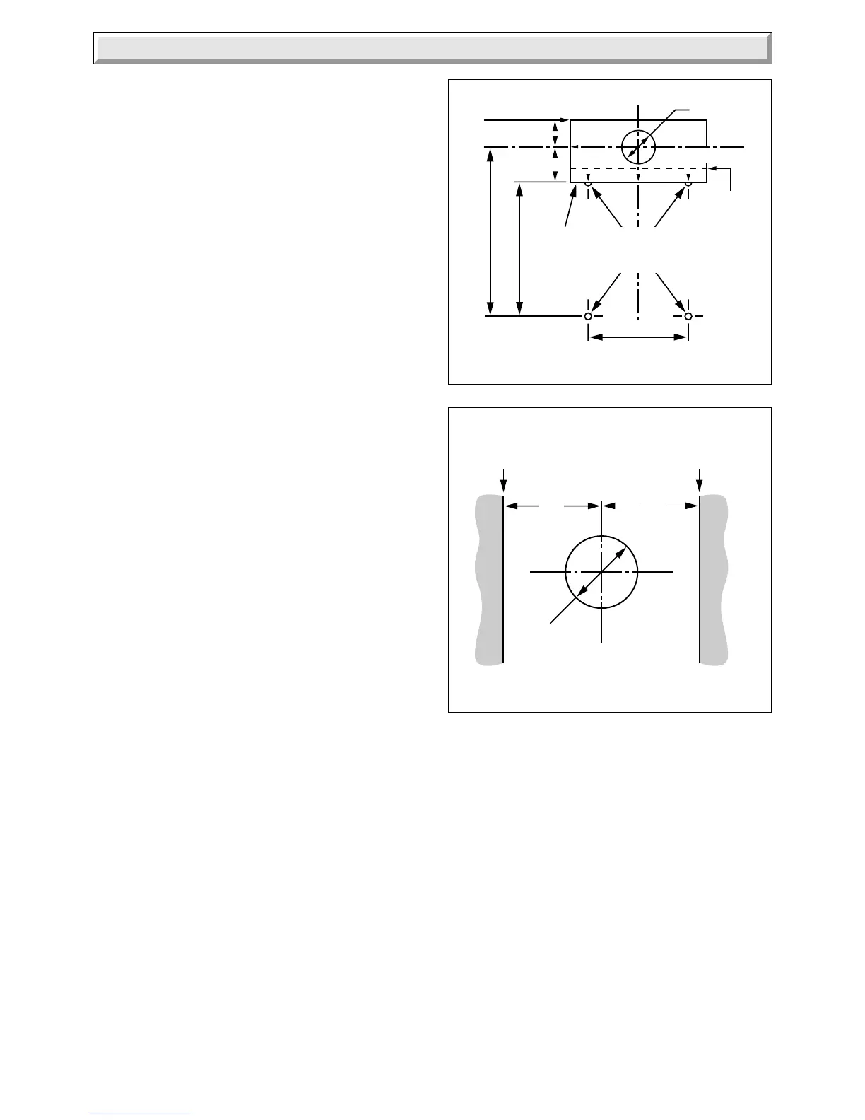
Position the flue template on the wall, the arrow points on the
centres of the two upper fixing points previously marked, see
diagram 6.4 which also shows dimensions.
For rear flue, mark the rear flue position as required, centre and/
or diameter.
For a side flue, mark the horizontal flue centre line at the sides
of the template. Extend the flue centre line horizontally left or
right to the internal corner where the flue is required to exit to
outside. Mark the position of the circular hole, on the flue exit
wall, using the dimensions given in diagram 6.5.
From the flue position marks, check that the flue terminal will be
in a suitable position, see diagram 3.6.
6.3 Flue Hole Cutting
Cut the hole horizontally in the wall, to the diameter shown in
diagram 6.4, using, preferably, a core drill.
6.4 Wall Sleeve
Note: If required, an optional Wall Liner, Part No. 900862, is
available, complete with fixing instructions.
6.5 Boiler Mounting Frame Fixing
Position the flue template over the flue hole and check the
position of the wall fixing points. Mark the position of the fixing
holes again, if required.
Drill the four fixing holes and insert wall plugs to suit No.10x50mm
long screws.
Secure the boiler mounting frame to the wall using No.10x50mm
long screws.
 Loading...


