40
221469B
4 Replacement of Parts
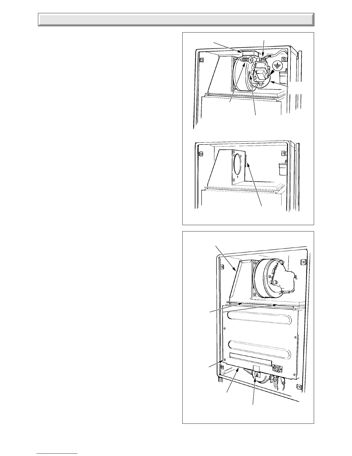
Diagram 4.1
Diagram 4.2
69076908
FLUE
ELBOW
ELECTRICAL CONNECTORS
SECURING
SCREW (2)
MOTOR/IMPELLER
SECURING SCREW (3)
(SHAKEPROOF WASHER
FOR EARTH CABLE)
LOCATION CLIP
FLUE COLLECTOR
SECURING
SCREWS
(2)
SCREW
(4)
COMBUSTION
CHAMBER
FRONT PANEL
WING NUT
EARTH
CABLE
4.1 Fan
Before starting refer to Section 1.1.
Isolate the boiler from the electrical supply, refer to Section 1.3.
Remove the outer case and the cover of the inner case, refer to
Section 1.4 and 1.5.
Disconnect the two electrical connectors at the fan, see diagram
4.1. It is not necessary to disconnect the green and yellow earth
cable.
Remove the fan, secured with two screws at the front, also
located into the flue elbow and clip at the rear.
To renew the motor and impeller, remove the three screws
securing it to the housing.
Transfer the earth cable to the replacement motor terminal
marked , fitting the earth cable and shakeproof washer when
securing the fan.
To fit the fan housing, locate it into the flue elbow and the clip at
the rear, push fully upward into the flue elbow to ensure a good
seal, then secure the fan with the two screws.
Connect the electrical cables, the polarity of the two connectors
is not important.
4.2 Main Burner
Before starting refer to Section 1.1
Isolate the boiler from the electrical supply, refer to Section 1.3.
Remove the outer case and the cover of the inner case, refer to
Sections 1.4 and 1.5.
Slacken the two screws securing the flue collector, see diagram
4.2.
Remove the combustion chamber front panel, secured with four
screws and a wing nut.
Separate the pilot assembly from the main burner secured with
two screws and washers, see diagram 4.3.
Remove the main burner from the main injector at the rear.
Raise the burner up and forwards, easing the pilot assembly
forwards to clear, taking care not to damage the combustion
chamber insulation or the pilot burner assembly.
Make sure that the main burner is fitted correctly on assembly,
located on the main injector and horizontal, the tips of the
rearmost blade under the two burner guides.
Locate the combustion chamber front panel under the front
edge of the flue hood on assembly, then secure all screws and
wing nut.
4.3 Main Injector
Before starting refer to Section 1.1.
Isolate the boiler from the electrical supply, refer to Section 1.3.
Remove the outer case and the cover of the inner case, refer to
Section 1.4 and 1.5.
Remove the main burner, refer to Section 4.2.
Unscrew the main injector.
Fit the new sealing washer supplied, to ensure gas soundness,
when fitting the main injector.
4.4. Pilot Burner
Before starting refer to Section 1.1.
Isolate the boiler from the electrical supply, refer to Section 1.3.
Remove the outer case and the cover of the inner case, refer to
Section 1.4 and 1.5.
 Loading...


