24
221469B
HONEYWELL
11 Commissioning
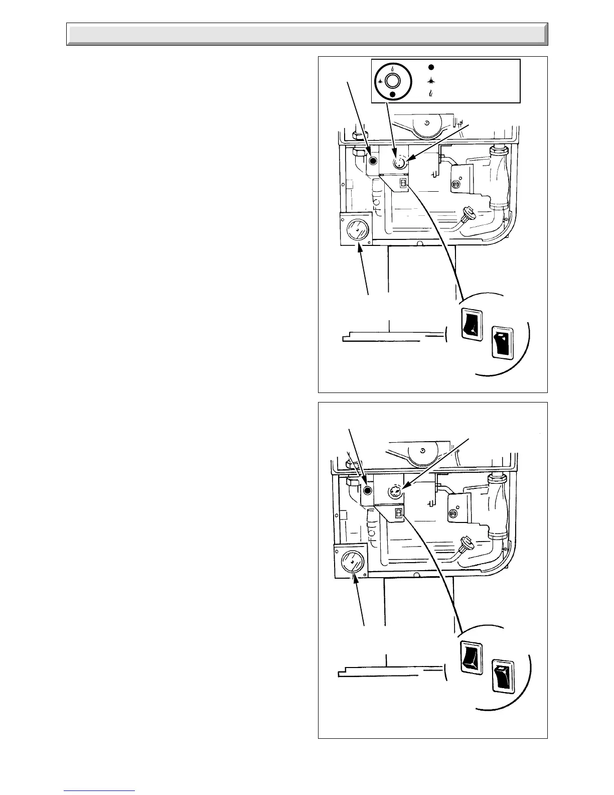
SIT
Diagram 11.1
4322
GAS CONTROL
KNOB 'D'
SWITCH
'ON'
SWITCH
(OFF)
PRESSURE
GAUGE 'A'
CENTRAL
HEATING
SELECTOR
SWITCH 'C'
Diagram 11.1
2834
SWITCH
'ON'
SWITCH
(OFF)
PRESSURE
GAUGE 'A'
CENTRAL
HEATING
SELECTOR
SWITCH 'C'
PIEZO
BUTTON 'E'
PIEZO
BUTTON
'E'
OFF
PILOT/IGNITION
MAIN BURNER
GAS CONTROL
KNOB 'D'
11.1 Filling Domestic Water Circuit
Check that the boiler is isolated from the electrical supply, at the
external isolator.
Fully open the domestic water supply stop cock or valve in the
supply to the boiler.
Open the two domestic water isolation valves, slots in line with
the length of the valve, see diagram 8.1.
Open all hot water draw-off taps and close them when water
flows. Check for water soundness of the whole domestic water
system and boiler.
11.2 Filling the Heating System
It is essential that a bypass is fitted in all installations, 22mm o.d.
minimum. The bypass must have a lockable valves “B” in
diagram 4.2, incorporated in a position so that inadvertent
closure or unauthorised interference is not possible.
The bypass MUST be fitted before any system control.
A radiator bypass is not recommended.
Open the two central heating isolating valves, slots in line with
the length of the valve, see diagram 8.1.
Flush, fill and vent the system refer to Section 4.9 “Filling Sealed
Systems”.
WARNING. SEVERAL COMPONENTS OPERATE ON MAINS
VOLTAGE AND WITH THE OUTER CASE REMOVED, LIVE
COMPONENTS BECOME EXPOSED.
To assist in filling and venting, the pump may be operated:
Connect the electrical supply, set switch “C” to “On”, white flash
showing, any remote heating systems controls, time switch
and/or room thermostat to call for heat, see diagram 11.1.
Note. If the clock/timer is fitted into the boiler, refer to the setting
instructions in the Instructions for Use.
Make sure that the automatic air vent is operating correctly, see
diagram 11.2.
Take care not to splash any of the electrical components.
Alternate the position of switch “C” between “On” and “Off”
positions to ensure that water flows through all parts of the boiler
and air is not trapped in the boiler internal bypass.
Pressurise the system until the pressure is 1.5bar (21.5lbf/in
2
).
Check the heating system and boiler for water soundness.
Check the operation of the safety valve by turning the safety
valve knob in the direction of the arrow.
Lower the pressure to the initial cold fill design pressure, refer
to Section 1.6 “Data”. Position the set pointer on the boiler
pressure gauge at this pressure also.
11.3 Preparation for Lighting
Isolate the boiler from the mains electrical supply at the external
isolator.
Test for soundness and purge air from the gas supply. Turn on
the gas service cock, slot in line with the length of the cock.
SIT only - Slacken the two piezo unit bracket screws and
remove the bracket, keyhole slot.
Slacken the burner pressure test point screw and connect a
suitable pressure gauge, see diagram 11.3.
 Loading...


