15
221469B
5 Domestic Hot Water System
5.1 General
The domestic hot water service must be in accordance with the
rules in force in the countries of destination.
5.2 Water Pressure
For the minimum and maximum working pressures of the
domestic hot water circuit of the boiler refer to Section 1.6 Data.
If the cold water supply pressure exceeds the maximum, a
governor must be fitted in the supply to the boiler to reduce the
pressure to within the limits given.
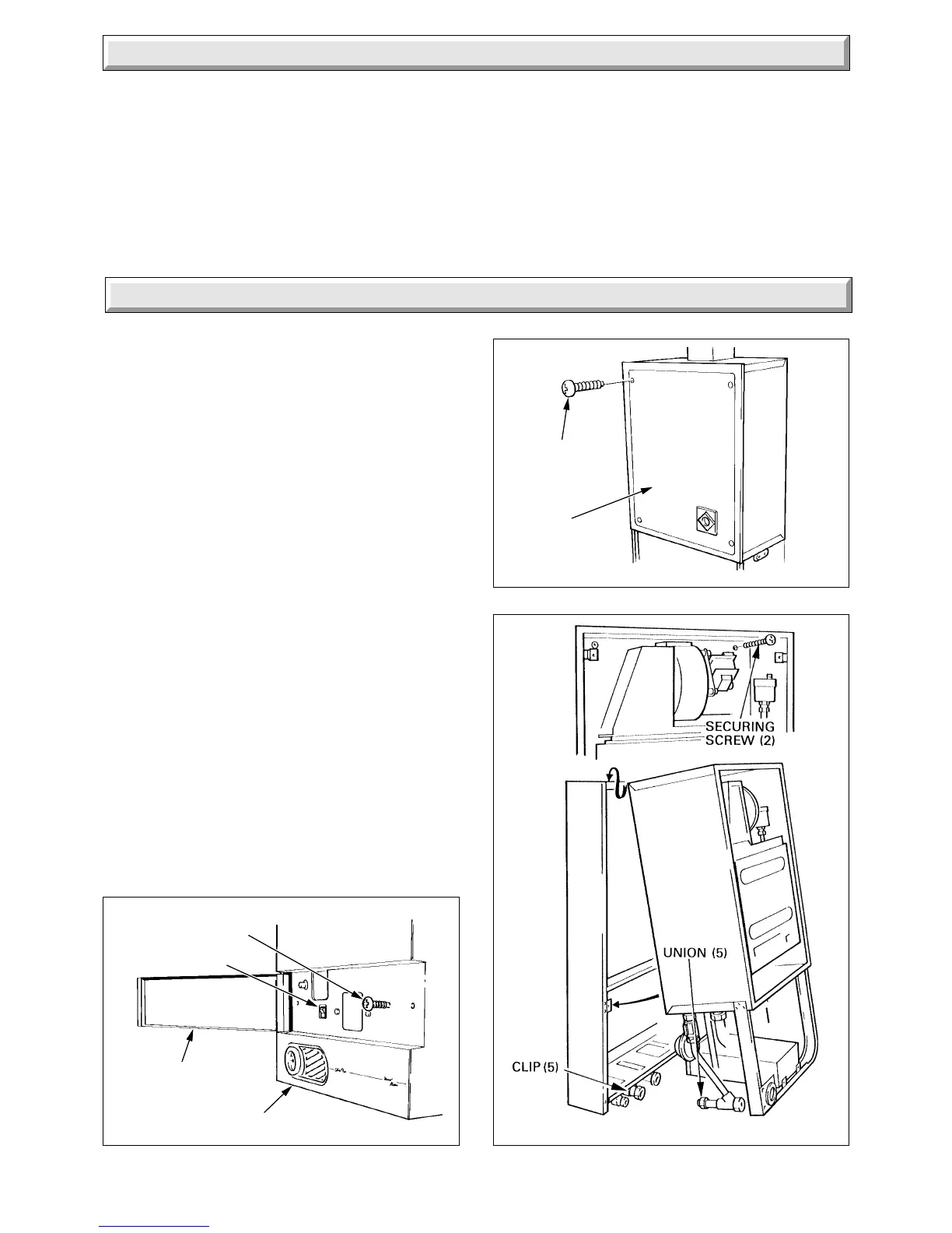
6.1 Unpacking
Remove the top carton and cut out the flue template from the
inner flap.
Open the control door, see diagram 6.1.
Remove the two screws securing the outer case and then lift it
at the top and pull it forwards and off.
Remove the cover of the inner case, secured with four screws,
see diagram 6.2.
Disconnect the gas service cock union and the front unions of
the isolation valves, see diagram 6.3.
Slightly loosen the clips of the gas service cock and the isolating
valves.
Remove the two boiler securing screws then remove the boiler
from the mounting frame, by pulling the studs from the clips and
unhooking it at the top.
6 Installation Preparation
Diagram 6.1 Diagram 6.3
OUTER CASE
SELECTOR SWITCH
OUTER CASE
SECURING SCREW (2)
DOOR
3893
INNER
CASE
COVER
SECURING
SCREW (4)
Diagram 6.2
2305 S
6910
5.3 “Hard” Water Areas
In areas where the water is “hard”, more than 200mg/litre, it is
recommended that a proprietary scale reducer is fitted in the
cold water supply to the boiler. Check the total water “hardness”,
using the kit supplied, in the door, following the instructions
given. Consult the local water company for additional advice.
A double check valve assembly must be fitted upstream of the
scale reducer. For the relative position of the scale reducer and
pressure reducing valve, if required, refer to the manufacturer’s
instructions.
 Loading...


