31
221469B
3.1 Initial Checks
If the boiler fails to operate, first check the following and put the
problem right, if possible.
Check that the electrical supply is available at the boiler and that
the fuses are in order.
Make sure that the system pressure gauge registers 0.7bar
minimum and that the automatic air vent works. Refer to
Installation Instructions Section 11.2.
The electronic control board of the boiler can be damaged by
incorrect testing with the power on.
Check that the gas supply is available at the boiler and purged
of air. Is the pilot burner lit?. If the pilot burner will not light, refer
to Section 3.2.
If the pilot burner fails to remain alight, refer to
Section 3.3.
Check that the boiler is set for the correct mode of operation.
With the central heating selector switch set to “Off”, check that
the domestic water supply is available and water flows freely
from the hot water taps.
With the central heating selector switch set to “On”, check that
all heating system controls, (if fitted) are working correctly and
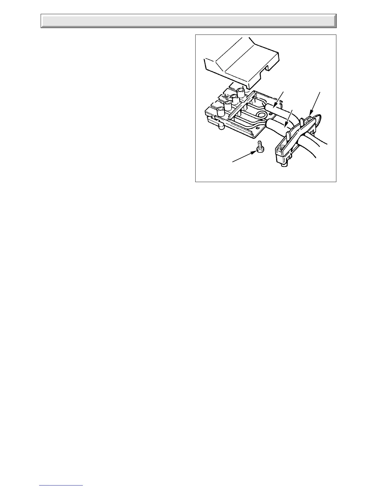
calling for heat. Isolate the boiler from the electrical supply.
Disconnect the rear multi-pole connector at the base of the
boiler and release the cable from the clamp. Remove connector
cover and test for continuity of the remote heating control circuit
at terminals 1 and 2, see diagram 3.1.
If there is continuity at these connections, carry on with the
detailed fault finding, refer to Section 3.4. If there is no
continuity, a remote heating system fault is indicated, which
must be put right.
3.2 Pilot Burner and Ignition System
Symptom. The pilot burner will not light or stay alight. Test the
pilot burner and ignition system as described in the fault finding
procedure, see diagram 3.2.
3.3 Thermocouple and Overheat Cutoff
On completion of initial checks as described in
Section 3.1.
Symptom. The pilot burner fails to stay alight.
Test the thermocouple, overheat cutoff and thermocouple
connectors, as described in fault finding diagram 3.3, see also
diagram 3.4.
Check the millivoltage of the thermocouple closed circuit at
points “A” and “E”, see diagram 3.4. This should be within the
range of 6 to 11mV.
Diagram 3.1
CABLE TO
REMOTE
HEATING
CONTROLS
MAINS
CABLE
CABLE
CLAMP
CABLE
CLAMP/COVER
SCREW (2)
6054
3 Fault Finding
 Loading...


