41
221469B
4 Replacement of Parts
Diagram 4.4HONEYWELL
Diagram 4.4
SIT
3083 S2321 S
2847 S
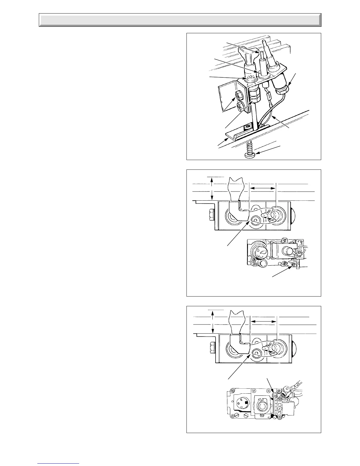
Diagram 4.3
SPARK
ELECTRODE
SEALING
ANGLE
PILOT TUBE
NUT
SECURING
SCREW AND
WASHER (2)
SECURING
SCREW
PILOT
INJECTOR
THERMO-
COUPLE
NUT
SCREW
IGNITION
LEAD
PILOT ADJUSTMENT SCREW
(ANTI-CLOCKWISE TO INCREASE)
SPARK GAP
3 to 4mm
12 to 14mm
12 to 14mm
SPARK GAP
3 to 4mm
PILOT ADJUSTMENT
SCREW
12 to 14mm
12 to 14mm
Remove the main burner refer to Section 4.2.
Remove the sealing angle, secured with a single screw, see
diagram 4.3.
Disconnect the ignition lead from the spark electrode.
Remove the spark electrode, secured with a single screw.
Disconnect the thermocouple nut from the pilot burner.
Disconnect the pilot supply tube, holding the pilot injector hexagon
with another spanner, then remove the pilot burner.
Check the spark gap upon assembly, see diagram 4.4.
4.5 Spark Electrode
Before starting, refer to Section 1.1.
Isolate the boiler from the electrical supply, refer to Section 1.3.
Remove the outer case and the cover of the inner case, refer to
Section 1.4 and 1.5.
Slacken the two screws securing the flue collector, see diagram
4.2.
Remove the outer combustion chamber front panel, secured with
the four screws and a wing nut.
Disconnect the ignition lead from the spark electrode, see diagram
4.3.
Remove the spark electrode, secured with a single screw.
Check the spark gap upon the assembly, see diagram 4.4.
4.6 Pilot Injector
Before starting, refer to Section 1.1
Isolate the boiler from the electrical supply, refer to Section 1.3.
Remove the outer case and the cover of the inner case, refer to
Section 1.4 and 1.5.
Remove the main burner, refer to Section 4.2.
Remove the sealing angle, secured with a single screw, see
diagram 4.3.
Disconnect the ignition lead from the spark electrode.
Remove the spark electrode, secured with a single screw.
Disconnect the thermocouple nut from the pilot burner.
Disconnect the pilot supply tube, holding the pilot injector hexagon
with another spanner, then remove the pilot burner.
Remove the pilot injector from the pilot assembly by unscrewing
it.
Check the pilot flame length on relighting, see diagram 4.4.
4.7 Thermocouple
Before starting refer to Section 1.1.
Isolate the boiler from the electrical supply, refer to Section 1.3.
Remove the outer case and the cover of the inner case, refer to
Section 1.4 and 1.5.
Remove the main burner, refer to Section 4.2.
Remove the sealing angle secured with a single screw, see
diagram 4.3.
Disconnect the ignition lead from the spark electrode.
Remove the control housing, secured with two screws. Support
the control housing on a surface or by screwing it to the front edge
of the base, using the outer case securing screw, see diagram 4.5.
 Loading...


