42
221469B
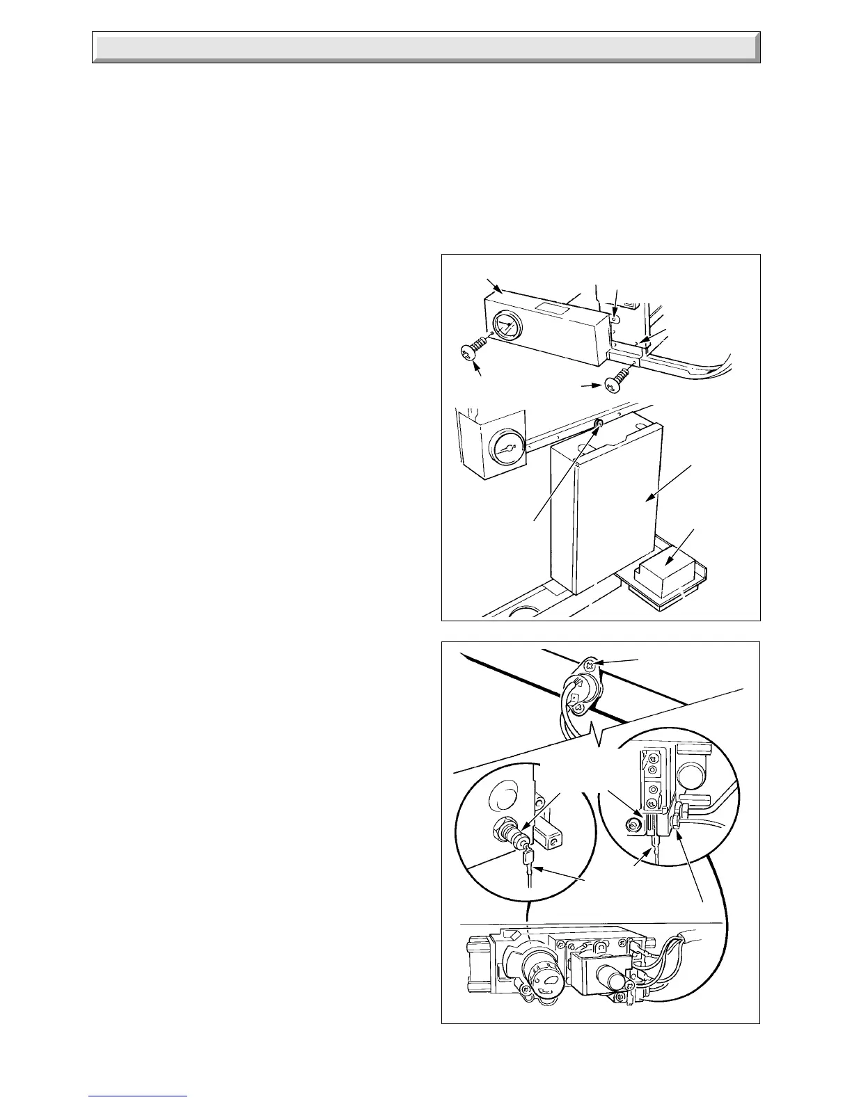
Diagram 4.6HONEYWELL
2799 S
ELECTRICAL
CONNECTORS
THERMOCOUPLE NUT
OVERHEAT
CUT-OFF
CONNECTORS
SECURING
SCREW (2)
4 Replacement of Parts
Diagram 4.5
3899 S
SECURING
SCREW
(To support the
control housing
if necessary)
CONTROL HOUSING
SECURING SCREW (2)
FASCIA
FASCIA
SECURING
SCREW (3)
CONTROL HOUSING COVER
SECURING SCREW
CONTROL
HOUSING
COVER
CLOCK/TIMER
Disconnect the pilot supply tube, holding the pilot injector
hexagon with another spanner, see diagram 4.3.
Disconnect the thermocouple at both ends, see diagram 4.3
and 4.6.
Remove the pilot burner, secured with two screws, then remove
the thermocouple.
Make sure that the overheat cutoff connector is in place in the
slot of the gas valve when fitting the thermocouple, Do not
tighten the thermocouple nut more than a quarter turn beyond
finger tight or make any tight bends in the thermocouple
capillary.
4.8 Boiler Overheat Cutoff
Before starting refer to Section 1.1
Isolate the boiler from the electrical supply, refer to Section 1.3.
Remove the outer case, refer to Section 1.4.
Gain access by removing the piezo bracket, disconnect lead,
see diagram 4.12.
Disconnect the boiler overheat cutoff electrical connectors from
the gas valve, see diagram 4.6.
Remove the overheat cutoff, secured with two screws.
Use a little of the heat sink compound supplied, between the
mounting plate and the cutoff when fitting it.
4.9 Domestic Hot Water High Limit Control.
Before starting, refer to Section 1.1.
Isolate the boiler from the electrical supply, refer to Section 1.3.
Remove the outer case, refer to Section 1.4.
Remove the control housing, refer to Section 4.7 paragraph 7.
Disconnect the electrical connector at the domestic hot water
high limit control, see diagram 4.8.
Remove the high limit control from the flow pipe, secured with
two screws.
Use a little of the heat sink compound supplied, between the
mounting plate and the control, when fitting it.
4.10 Piezo Unit
Before starting refer to Section 1.1
Isolate the boiler from the electrical supply, refer to Section 1.3.
Remove the outer case, refer to Section 1.4.
Remove the piezo unit bracket, see diagram 4.12.
Disconnect the ignition lead at the piezo unit.
Remove the piezo unit from the bracket.
4.11 Ignition Lead
Before starting refer to Section 1.1.
Isolate the boiler from the electrical supply, refer to Section 1.3.
Remove the outer and inner case, refer to Section 1.4 and
1.5.
Disconnect the ignition lead at both ends and remove it. Take
care not to damage the seals when passing the connectors
between them.
Make sure that the clear insulated connector is fitted to the
spark electrode and the lead follows the same route, being
secured in the same manner as the original.
4.12 Pressure Gauge
Before starting, refer to Section 1.1.
Isolate the boiler from the electrical supply, refer to Section 1.3.
Remove the outer case, refer to Section 1.4.
Release the water pressure and drain the central heating circuit
of the boiler, refer to Section 1.3 and 1.6.
Remove the control housing, refer to Section 4.7 paragraph 7.
Remove the pressure gauge bracket, see diagram 4.7.
 Loading...


