43
221469B
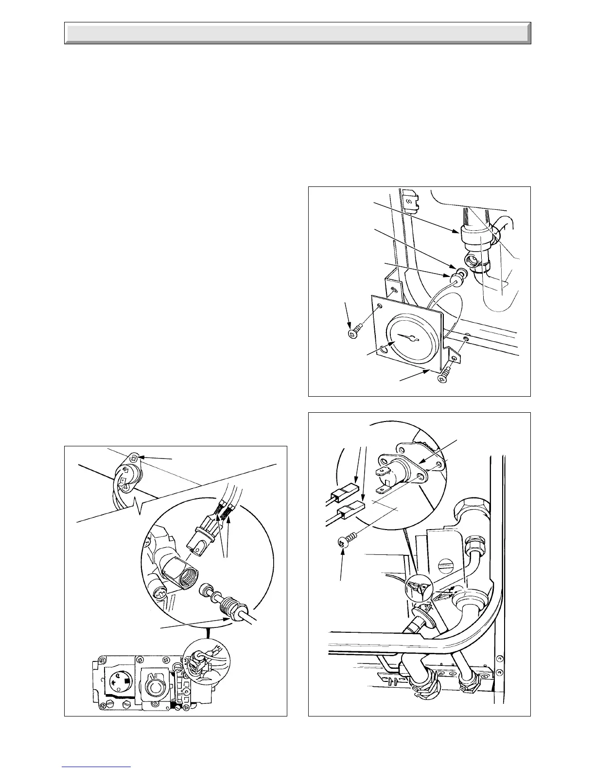
Diagram 4.7
Diagram 4.8
4 Replacement of Parts
2831 S
4449 S
PRESSURE
GAUGE
SAFETY
VALVE
SEALING
WASHER
PRESSURE
GAUGE
CONNECTION
SECURING
SCREW (2)
PRESSURE
GAUGE BRACKET
SECURING
SCREW (2)
ELECTRICAL
CONNECTORS
D.H.W. HIGH
LIMIT CONTROL
Diagram 4.6
SIT
2865 S
ELECTRICAL
CONNECTORS
SECURING
SCREW (2)
THERMOCOUPLE
NUT
Disconnect the pressure gauge connection from the safety
valve, discard the sealing washer.
Remove the pressure gauge secured with the retaining spring
tabs.
Locate the supplied sealing washer under the pressure gauge
connection when it is fitted to the safety valve.
Make up the water loss and pressurise the system, refer to
Commissioning in the Installation Instructions.
4.13 Control Boards
Before starting refer to Section 1.1.
Isolate the boiler from the electrical supply, refer to Section 1.3.
Remove the outer case, refer to Section 1.4.
Remove the clock mounting bracket securing screws, see
diagram 4.8A.
Remove control housing cover, temperature control knob and
the fascia, see diagram 4.5.
Remove the control housing assembly, see Section 4.13.
Disconnect all the multi-pin connectors, see diagram 4.9.
Remove the control boards from the support post, noting the
correct positions. Great care must be taken when handling any
control board.
THEY MUST BE KEPT IN THE ANTI-STATIC HOLDER UNTIL
IMMEDIATE REQUIREMENT.
To connect the multi-pin connector correctly, see diagram 4.10.
Check and adjust the main burner gas pressure in the hot water
and central heating modes, if necessary, refer to Commissioning
in the Installation Instructions.
4.14 Clock/Timer - if fitted
ELECTRO/MECHANICAL and DIGITAL clock/timer - Release
the mounting bracket securing screws, see diagram 4.8A.
Disconnect electrical cables, release securing clip to remove
the clock timer and spacer, see diagram 4.8B.
 Loading...


