44
221469B
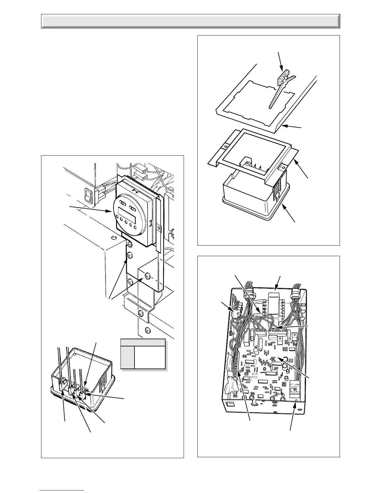
4 Replacement of Parts
Diagram 4.9
5722
MULTI-PIN
CONNECTOR (4)
ELECTRICAL
CONNECTOR (6)
TRANSFORMER
SECURING
SCREW,
WASHER
AND NUT
SUPPORT
POST (4)
CONTROL
BOARD
FOUR
WAY
TERMINAL
BLOCK
Diagram 4.8B
SECURING CLIP (2)
SPACER
PLATE
MOUNTING
BRACKET
TIMER/CLOCK
6515
KEY
br BROWN
b BLUE
y YELLOW
6507
Diagram 4.8A
CLOCK/
TIMER
ELECTRICAL
CONNECTIONS
MAINS
NEUTRAL (N)
MAINS
LIVE (L)
HEATING ON
COMMON
y
y
br b
SECURING
SCREWS (2)
4.15 Transformer
Before starting, refer to Section 1.1
Isolate the boiler from the electrical supply, refer to Section 1.3
Remove the outer case, refer to Section 1.4.
Remove the control housing and cover, refer to
Section 4.13.
Support the control housing, see diagram 4.5.
Disconnect the electrical connectors from the transformer, see
diagram 4.9.
Remove the transformer, noting the correct position.
To connect the transformer cables correctly, see diagram 4.10.
 Loading...


