53
221469B
4 Replacement of Parts
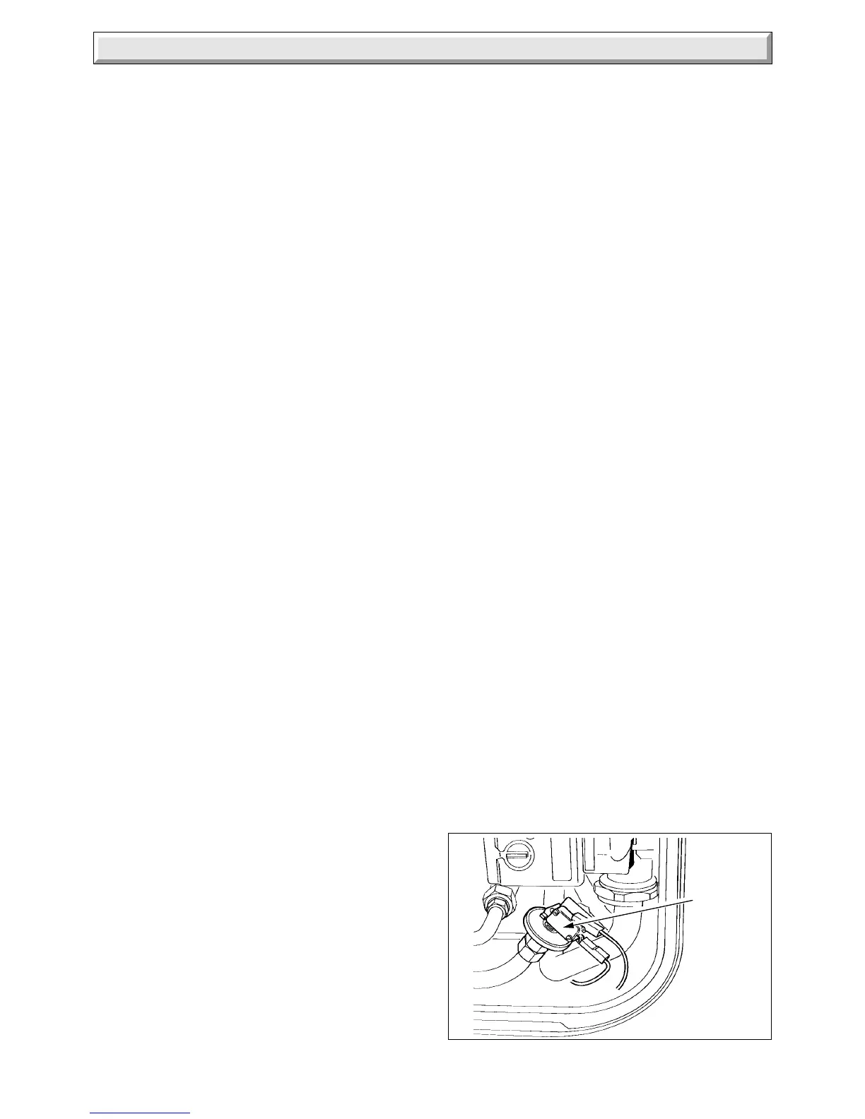
Diagram 4.21
4816
WATER
PRESSURE
SWITCH
4.29 Heat Exchanger
Before starting refer to Section 1.1
Isolate the boiler from the electrical supply and close the gas
service cock, refer to Section 1.3.
Remove the outer case and the cover of the inner case, refer to
Section 1.4. and 1.5.
Release the water pressure and drain, refer to Section 1.6.
Remove the fan from the flue collector, refer to Section 4.1.
Remove the flue collector, secured with two screws, see diagram
4.2.
Remove the main burner, refer to Section 4.2.
Remove the automatic air vent, see diagram 4.20.
If renewing the heat exchanger, transfer the air vent to the new
one, using the new sealing washers supplied.
Disconnect the union nuts of the heat exchanger to remove it.
Discard the sealing washers and use the new ones supplied,
upon assembly.
Locate the raised location tabs on the combustion chamber
sides into the slots on the heat exchanger, when fitting.
Make sure that the main burner is located on the main injector
and is horizontal, the tips of the rear most blade under the two
burner guides.
The combustion chamber front panel should be fitted loosely,
then the flue collector also fitted loosely, ensuring that it is
seated correctly on the heat exchanger and over the top edge
of the front panel.
Locate the fan into the flue elbow and the clip at the rear, then
secure with the two screws.
Connect the cables, the polarity of the two connectors is not
important.
Tighten the wing nut and screws evenly to secure the flue
collector and combustion chamber front panel.
Make up water loss and pressurise the system, refer to
Commissioning in the Installation Instructions.
4.30 Combustion Chamber Insulation
Before starting refer to Section 1.1.
Isolate the boiler from the electrical supply and close the gas
service cock, refer to Section 1.3.
Remove the outer case and the cover of the inner case, refer to
Section 1.4 and 1.5.
Remove the fan, refer to Section 4.1.
Remove the flue collector, secured with two screws, see diagram
4.2.
Remove the combustion chamber front panel, secured with four
screws and a wing nut.
Remove the front insulation panel, secured with a clip, see
diagram 4.22.
Slide out both side insulation pieces.
Pull the lower rear insulation forwards, then slide the upper rear
insulation down from behind the heat exchanger.
To fit the flue collector, combustion chamber front panel and
fan, refer to Section 4.29.
4.31 Expansion Vessel
Renewal of the expansion vessel requires the boiler to be
removed from the wall. As an alternative, in certain
circumstances, a separate expansion vessel of the same
specification may be connected as close as possible to the
boiler, leaving the original in position.
Before starting refer to Section 1.1
Isolate the boiler from the electrical supply and close the gas
service cocks, refer to Section 1.3.
Remove the outer case and the cover of the inner case, refer to
Section 1.4. and 1.5.
Release the water pressure and drain, refer to Section 1.6.
Remove the fan from the flue collector, refer to Section 4.1.
Remove the flue elbow, secured to the boiler with four screws
and to the air duct with two screws, see diagram 4.23.
Disconnect the boiler water connection union nuts at the front
of the isolating valves, see diagram 1.1.
Disconnect the gas service cock union.
Disconnect the safety valve discharge compression fitting nut at
the rear of the boiler.
Separate the two parts of the boiler multi-pole connector.
Slacken the clips of the gas service cock and isolating valves.
Remove the boiler from the mounting frame, secured with two
screws at the top, see diagram 4.23. Pull the boiler from the
isolating valves and clips at the bottom, taking care not to loose
the water filter from inside the boiler inlet. Unhook the boiler at
the top and withdraw it forwards.
Carefully lay the boiler down on its side to gain access to the
expansion vessel.
Disconnect the union nut connection, see diagram 4.24.
Remove the expansion vessel, secured with three clamps.
Discard the sealing washer and use the new one supplied,
when fitting.
Connect the union nut, when fitting the expansion vessel,
before clamping it.
To fit the flue collector, combustion chamber front panel and
fan, refer to Section 4.29.
Make up water loss and pressurise the system, refer to
Commissioning in the Installation Instructions.
Reminder - Leave these instructions with the user.
 Loading...


