8.1 Systems Connection
NOTE: The appliance may contain a small amount of water,
place a water container beneath the boiler connections.
Remove the protective caps from the boiler connections.
Assemble and secure the pre formed copper tails to their
respective isolation valves making sure of their correct
orientation, see diagram 8.1.
Fit the isolation valves/copper tails with seals to the appliance
as shown in diagram 8.1
Make sure that all connections are secured in the sequence
shown on diagram 8.1. There are ats on the body of the
valves for locating a spanner to aid tightening.
Fit the ‘O’ ring seal from the loose items pack to the Double
Check Inlet Valve assembly then secure into isolation valve
with wire retaining clip, see diagram 8.1.
13239
Diagram 7.2
7 Boiler Fixing
Fit the Central Heating Isolation Valve handles and secure
with screws provided.
Plumb the system pipe work to the copper tails.
NOTE: Do not subject the isolation valves to heat and make
sure that the test and drain points are accessible, see diagram
8.1.
Flush out the domestic hot water and the heating systems,
refer to section 5.8.
The whole of the gas installation, including the meter, should
be inspected, tested for tightness and purged in accordance
with the current issue of BS6891 and in IE the current edition
of I.S.813 “Domestic Gas Installations”.
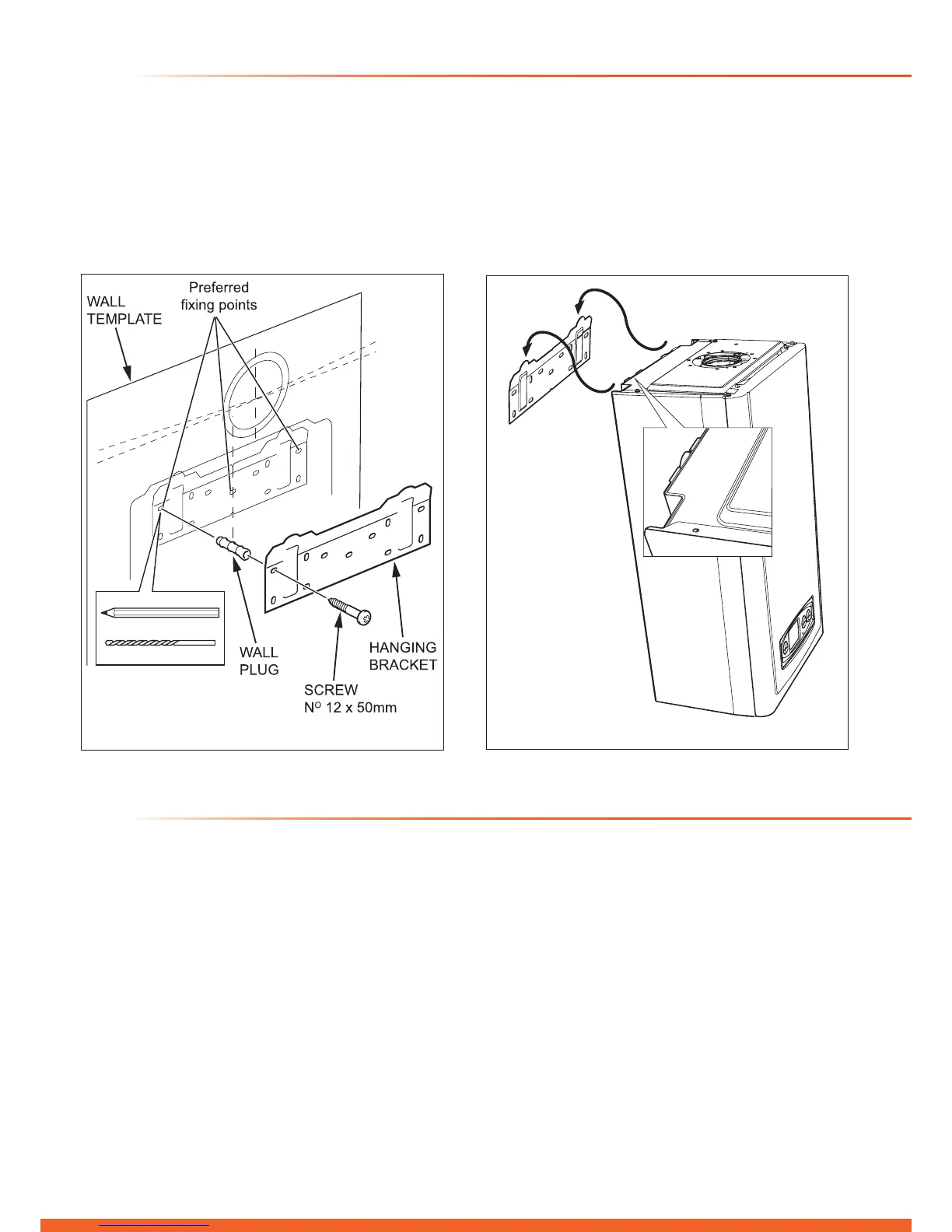
7.1 Hanging Bracket Fixing
The Wall Hanging Bracket is supplied in the main boiler
packaging at the rear of the boiler.
Reposition the wall template over the ue hole and mark
the position of the xing holes for the hanging bracket, see
diagram 7.1.
Drill xing holes and insert suitable wall plugs.
Diagram 7.1
13503
7.2 Boiler Hanging
IMPORTANT: With regards to the Manual Handling
Operations, 1992 Regulations, the following lift operation
exceeds the recommended weight for a one man lift, refer to
section 17 Manual Handling.
Lifting the boiler into position, lean the top of the boiler slightly
to the wall and position just above the hanging bracket. Lower
the boiler slowly and engage onto the hanging bracket, see
diagram 7.2.
8 Gas / Water Connections

 Loading...


