14 Fault Finding
Diagram 14.1
13535
14.1 Preliminary fault nding
The following checks should be performed before proceeding
onto specic diagnostics:
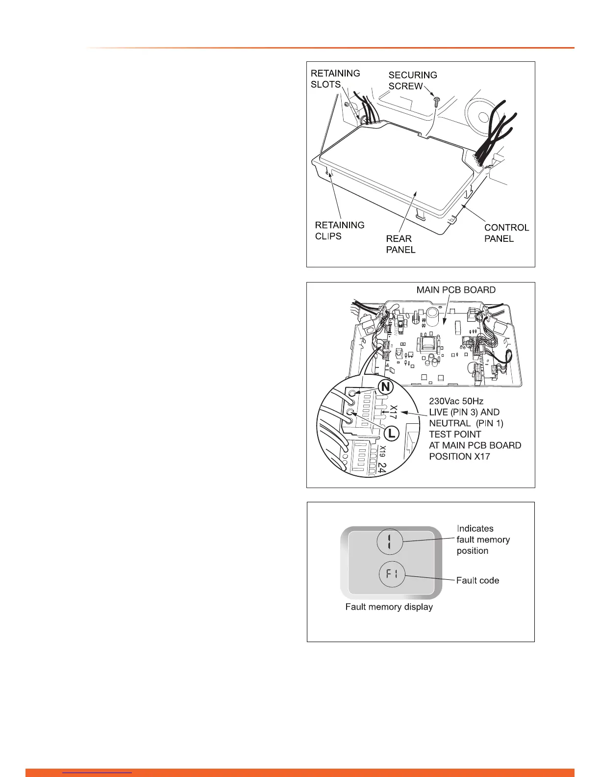
• Check the external electrical supply to the boiler is on and
a supply of 230V is present at the ‘L’ and ‘N’ terminals on
the installer interface, refer to section 11.4 for access and
diagram 14.4.
• Check the electrical installation and appliance, carry
out tests for earth continuity, polarity, short circuit and
resistance to earth, using a suitable multimeter.
An aid to test
Remove the front casing panel, see diagram 13.2 and the
control panel securing screw, see diagram 14.1 then lower
into service the position.
Remove the rear panel by prising the retaining clips, see
diagram 14.1.
Carry out the tests at connector plug X17, see diagram 14.2.
Check chassis earth at a bare metal point on the boiler.
• Check that there is a gas supply to the boiler and the gas
service isolation valve is turned on, see diagram 12.2.
• Check pressure at the gas service isolation valve, refer to
section 12.5.
• Check that the heating system pressure indicates at least
1mb, if not, ll and vent the system as described in section
12.2.
• Check that all external controls are on.
• Check the functional ow diagram, 14.5.
14.2 Fault Codes
Fault codes take priority over all other display functions in the
event of a fault occurring, refer to diagram 14.6.
If multiple faults occur the codes will be displayed for approx.
2 seconds, alternatively.
14.3 Fault Memory
The Fault memory stores details of the ten most recent faults.
To access this menu, refer to diagram 14.3:
a) Press and hold ‘MODE’ for 5 seconds.
b) When the display shows a ashing ‘0’ press ‘MODE’
button.
c) Press a ‘+’ button to scroll back through the fault memory
(Position 1 is most recent), see fault memory display.
To exit this menu, press the ‘MODE’ button.
14.4 Diagnostic Menu
The Diagnostic Menu provides the ability to view and
change certain parameters. See diagram 14.7 for available
parameters.
14.5 Status Codes
The status codes provide information about the current
operating condition of the boiler and can be accessed through
the diagnostic display, refer to diagram 14.8.
13452
Diagram 14.3
Diagram 14.2
13845

 Loading...


