15 Replacement of Parts
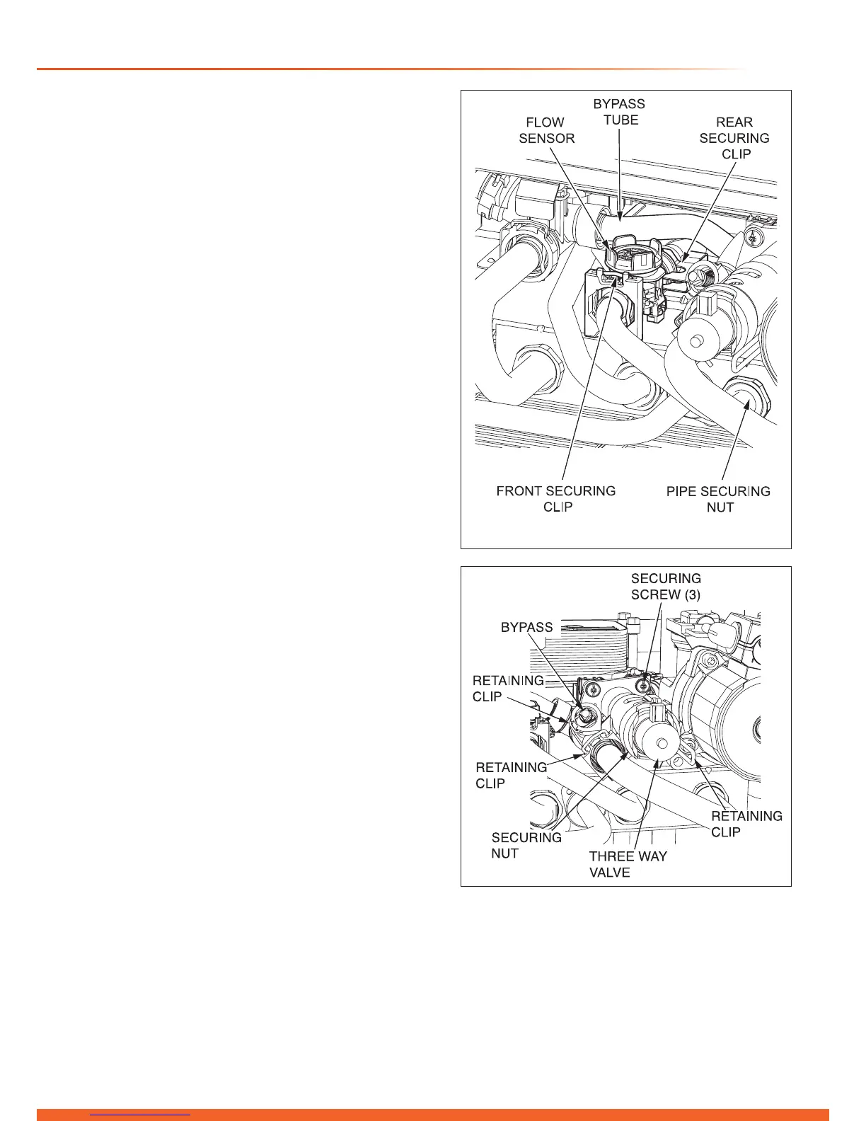
15.22 Flow Sensor
For access, refer to section 15.1.
Drain the boiler hot water circuit as described in the
appropriate section of 15.1.
Refer to diagram 15.17.
Remove the front securing clip.
Disconnect the domestic cold water pipe at the bulkhead
connection and remove the pipe.
Remove the rear securing clip.
Disengage the ow sensor housing.
Remove the electrical connection.
Fit new ‘O’ rings.
After replacing the ow sensor, open the cold-water isolation
valve and slowly open a hot water tap to remove air.
15.23 Bypass
For access, refer to section 15.1.
Drain the boiler heating circuit as described in the appropriate
section of 15.1.
Refer to diagram 15.18.
Remove the retaining clip to remove the bypass screw.
Fit new ‘O’ rings.
After replacing the bypass, rell, vent and pressurise the
boiler.
15.24 Three Way Valve
For access, refer to section 15.1.
Drain the boiler heating circuit as described in the appropriate
section of 15.1.
Refer to diagram 15.18.
Remove the retaining clips and three securing screws to
remove the three way valve.
Undo the securing nut to check the solenoid actuator, spindle
and shaft.
Fit new ‘O’ rings before replacing the three way valve
assembly.
Rell, vent and pressurise the boiler.
15.25 Plate-to-Plate Heat Exchanger
For access, refer to section 15.1.
Drain the boiler heating and domestic hot water circuits as
described in the appropriate sections of 15.1.
Refer to diagram 15.19.
Remove the 4 securing screws.
Remove the plate-to-plate heat exchanger by lifting it up and
over the top of the left hand hydroblock.
When replacing the plate-to-plate heat exchanger ensure that
the four rubber sealing washers are tted into the hydroblock.
NOTE: The plate-to-plate heat exchanger only ts one way.
Rell, vent and pressurise the boiler.
Diagram 15.17
13282
Diagram 15.18
13259

 Loading...


