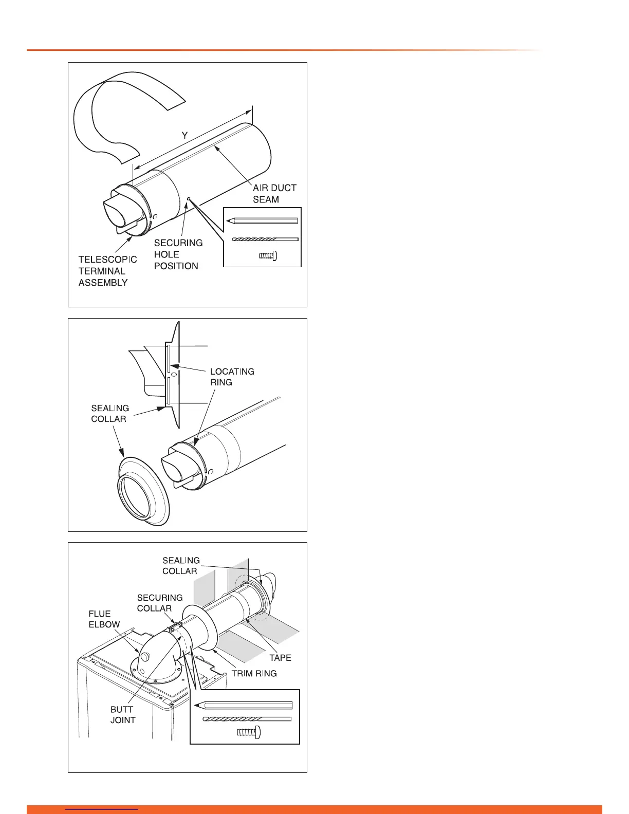
Diagram 10.7
12929
Diagram 10.8
12977
Diagram 10.9
13254
10 Telescopic Flue - Length, Preparation and Installation
10.4 SIDE Flue
With the ue elbow temporarily tted, measure the distance
from the outside wall to the butt joint, see diagram 10.6. If the
measurement ‘Y’ exceeds 525mm, then the appropriate length
of extension pipe is required.
If the dimension is less than 315mm DO NOT cut the ue, it
can project to a maximum of 600mm, refer to diagram 10.5. If
this is not desirable then a Standard ue MUST be used and
cut to length.
10.5 Flue Fitting
IMPORTANT:-
The ue seals are sensitive to mineral oil based lubricants. Do
not grease the seals. If the seals do need to be lubricated
use only water.
During the installation of the ue system, ensure that debris
such as mortar, lings or swarf are cleared from the ue
system before completion.
Inspect the ue pipes before tting and do not install damaged
or dented ue components.
When assembling the ue system, ensure that the inner
seals are not damaged, do not install a ue component with a
damaged seal.
When tting ue elbows ensure that they are tted at the
correct angle to avoid strain, this will ensure that the seal ts
correctly preventing leakage.
With the air duct seams aligned and the ue set to the
required length ‘Y’, mark the securing hole position in the air
duct. Drill a 3mm diameter hole at this position, take care not
to pierce the inner ue duct. Secure with screw provided and
tape the joint, see diagram 10.7.
Fit the sealing collar onto the locating ring on the ue terminal,
see diagram 10.8.
With the ue elbow removed, push the ue assembly into
the wall, externally or internally, until the end of the assembly
protrudes a short way from the inside face of the wall. This
will enable the internal trim ring (if required) to be positioned
and allow the ue assembly to be drawn back up to the ue
elbow.
Secure the ue elbow in position on top of the boiler with the
four screws supplied.
Draw the ue assembly from wall and engage the ue duct
into the elbow and butt t between the air duct and ue elbow.
Fit the securing collar into position.
Ensuring correct alignment of the ue, mark through two of the
pre drilled holes in the securing collar.
Remove securing collar and drill two 3mm diameter holes one
in the elbow and one in the air duct, take care not to pierce the
inner ue duct. Fit the securing collar and secure with screws
provided, see diagram 10.9.
Slide the internal trim ring back against the wall, securing in
place with a small amount of sealant if required.
The cut ducts must be de-burred and all lings and debris
removed.
Insert the ue duct into the air duct terminal assembly,
remembering to engage the catch within the terminal.
Check that the outer rubber sealing collar makes an effective
seal against the wall face.

 Loading...


