11.2 System Controls 24V
WARNING: UNDER NO CIRCUMSTANCES MUST
ANY MAINS VOLTAGE BE APPLIED TO ANY OF THE
TERMINALS ON THE 24V CONNECTION PLUG.
Connect the mains supply and system heating controls e.g.
room thermostat as diagram 11.2. External controls should be
tted in accordance with the rules in force.
If tting a proprietary programmer as part of the system
controls the internal programmer will need to be disabled as
described in section 11.6.
If tting the Glow-worm Climapro programmer, the internal
programmer will automatically be disabled.
11.3 Mains Voltage System Controls
WARNING: UNDER NO CIRCUMSTANCES MUST
ANY MAINS VOLTAGE BE APPLIED TO ANY OF THE
TERMINALS ON THE 24V CONNECTION PLUG.
Connect mains supply and system controls as diagram 11.3.
External controls should be tted in accordance with the rules
in force.
If tting a proprietary programmer as part of the system
controls the internal programmer will need to be disabled as
described in section 11.4.
If tting the Glow-worm Climapro programmer, the internal
programmer will automatically be disabled.
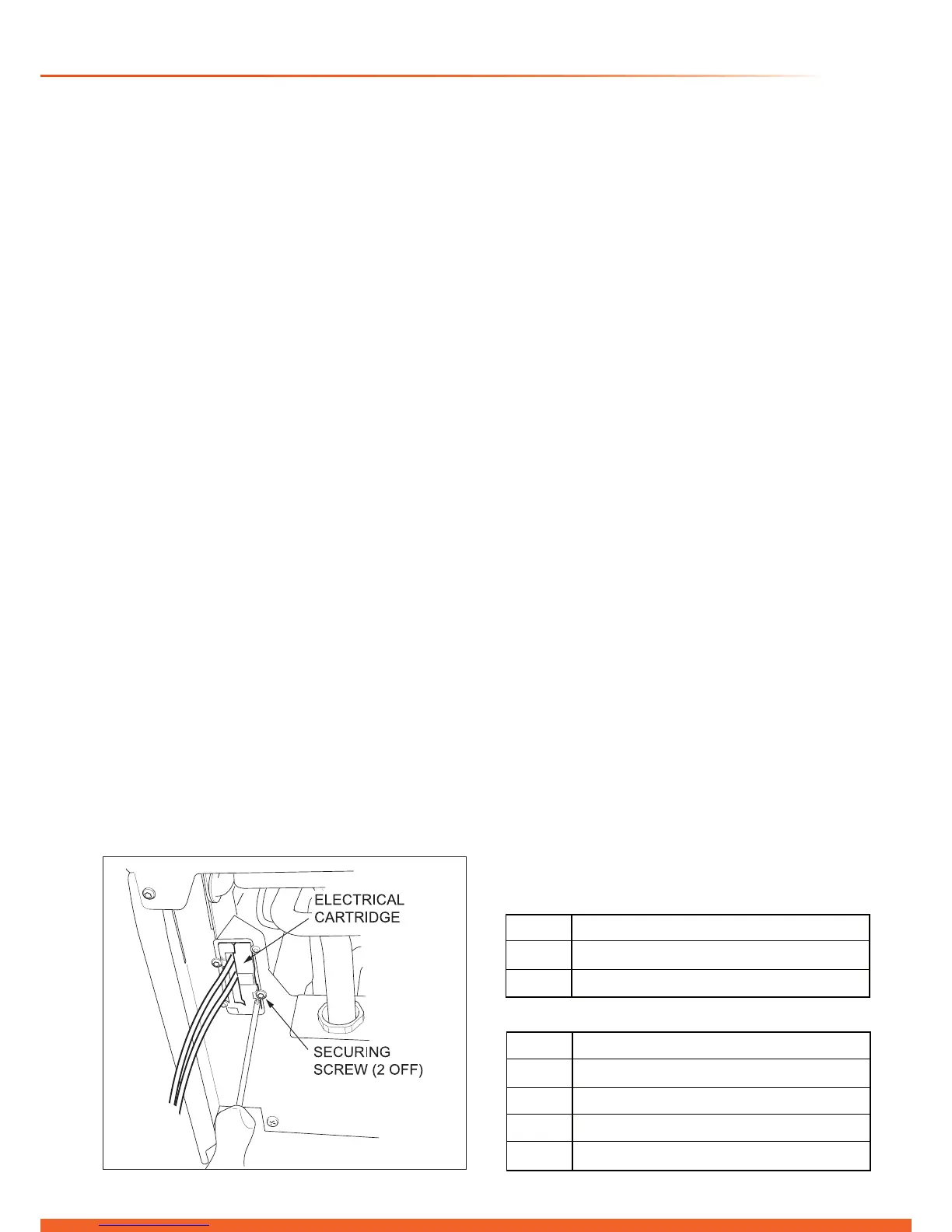
11.4 Electrical Cartridge Securing
With the gas service isolation valve closed and with no
demand from any external controls, t the electrical cartridge
into the interface housing, see diagram 11.4.
Secure with the two cartridge retaining screws provided in the
cartridge body.
11.5 Electrical Connections - Testing
Carry out preliminary electrical system checks as below:
1. Test insulation resistance to earth of mains cables.
2. Test the earth continuity and short circuit of cables.
3. Test the polarity of the mains.
Note: If you require to test the appliance refer to section 14.
Switch on the power to the appliance. The appliance should
display that it is in the “OFF” mode, refer to diagram 12.1.
If not, press the “Mode” button repeatedly until the “OFF”
symbol is displayed, then continue as follows:
11 Electrical Connection
13488
11.6 Disabling the internal Programmer
Fitting an external proprietary Programmer will require that
you disable the Internal Programmer, refer to diagram 12.1.
a) Press and hold the ‘mode’ button for 5 seconds.
The display will change to ashing ‘0’.
b) Use the ‘+’ or ‘-’ button to scroll to 96.
c) Press ‘MODE’ to conrm.
d) The display now shows a ashing ‘d. 0’ Use the ‘+’ or
‘-’ key to scroll to ‘d.92’.
e) Press ‘MODE’ to conrm.
f) The display now shows a ashing ‘2’ above the ‘d.92’.
g) Use the ‘+’ or ‘-’ button to change this value to ‘0’.
h) Press ‘MODE’ to conrm, ‘1’ stops ashing and is saved.
i) Press and hold ‘MODE’ to exit.
The internal Programmer has now been disabled.
See the diagnostic menu instructions in the Fault Finding
section for further details.
11.7 Internal Programmer Conguration
The internal programmer is factory set in the 24hr. CH mode
with the following pre-set timed intervals:
Monday - Friday ON 6.00 - OFF 8.00
ON 16:00 - OFF 23.00
Saturday - Sunday ON 8.00 - OFF 23.00
The DHW pre-heat is also factory set with the following pre-
set timed intervals :
Monday - Sunday ON 6.00 - OFF 24.00
If required the internal 24 hour Central Heating mode can be
changed to the 7 day mode, by following the procedure below:
a) Press and hold the ‘mode’ button for 5 seconds.
The display will change to ashing ‘0’.
b) Use the ‘+’ or ‘-’ button to scroll to 96.
c) Press ‘MODE’ to conrm.
d) The display now shows a ashing ‘d. 0’ Use the ‘+’ or
‘-’ key to scroll to ‘d.91’.
e) Press ‘MODE’ to conrm.
f) The display now shows a ashing ‘0’ above the ‘d.91’.
g) Use the ‘+’ button to change this value to ‘1’.
h) Press ‘MODE’ to conrm, The value is now saved.
i) Press and hold ‘MODE’ to exit.
It is possible to enable a second programmer channel to
control the DHW circuit pre-heat function. Follow the same
procedure as described above but scroll to ‘d.92’ and change
the value to ‘3’.
The following two tables outline the conguration options:
Diagram 11.4
d.92 Enable/disable internal programmer
0 CH OFF / DHW OFF
1 CH OFF / DHW ON
2 CH ON / DHW OFF
3 CH ON / DHW ON
d.9124 hour / 7 day Operation
0 24 HOUR
1 7 DAY
Table 1
Table 2

 Loading...


