As an option, a chargeable boiler only commissioning service
can be provided by Glow-worm Service by calling telephone
No. 01773 828100.
12.9 LPG CONVERSION - all models
NOTE: Steps 12.1 and 12.3 will need to be completed before
the appliance can be converted.
This conversion should only be carried out by a competent
person approved at the time by the Health and Safety
Executive.
During the conversion to Propane use of a suitable ue gas
analyser is necessary.
● The person carrying out a combustion measurement should
have been assessed as competent in the use of a ue gas
analyser and the interpretation of the results.
● The ue gas analyser used should be one meeting the
requirements of BS7927 or BS-EN50379-3 and be calibrated in
accordance with the analyser manufacturers’ requirements.
● Competence can be demonstrated by satisfactory comple-
tion of the CPA1 ACS assessment, which covers the use of
electronic portable combustion gas analysers in accordance
with BS 7967, parts 1 to 4.
Tools required to make the conversion are a 2mm Allen key
and an electricians screwdriver.
Having checked :
● the appliance and system have been installed in
accordance with the instructions.
● the integrity of the ue system and ue seals....
● the integrity of the appliance combustion circuit and
relevant seals....
● that all internal/external controls are calling for heat.
● the gas service isolation valve ‘F’, diagram 12.2, is open
(1) Gain access the gas valve, by removing the front and
inner casing panels, see diagram 13.2.
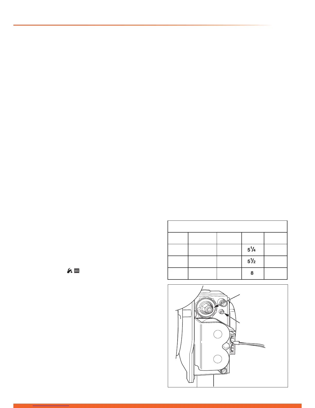
(2) Refer to diagram 12.5 and turn the gas valve throttle fully
clockwise.
(3) Turn the throttle anti-clockwise by the number of turns
shown in the table.
(4) Ensure that the gas analyser is set to the correct fuel
setting - Propane.
(5) Attach combustion analyser to the combustion test point,
refer diagram 13.1.
IMPORTANT: Remember to replace the cap on
completion of the test.
(6) Select the “
”, constant central heating with DHW
function by pressing the “Mode” button repeatedly. The
boiler should re automatically.
The appliance will enter a self checking routine, then the
fan will start and the ignition sequence commence.
The boiler, if necessary, will automatically repeat the
ignition sequence a further 4 times.
If the burner fails to ignite the display will show “F1”.
Initially this may be due to air in the gas supply line.
Depress the ‘reset’ button on the fascia to clear the
display and the ignition sequence will be repeated.
If the appliance still does not light & goes “F1”, turn the
throttle anti-clockwise a further turn and press the reset
button. The appliance will (after a short delay) again
attempt to re. Repeat this procedure, up to a total of 2
extra turns on the throttle screw, until the appliance lights.
(7) Check and adjust the burner %CO
2
at maximum rate.
Press the “reset” button on the controls fascia, release
and immediately press and hold in the “+” button. After
approximately 5 seconds “Hi” will be displayed. Pressing
the mode button when “Hi” is selected will force the boiler
to maximum rate, the display will ash between “Hi” and
the “default display” this will indicate the boiler has been
forced to maximum.
Natural Gas (G20) to LPG (G31) Conversion
15440
Diagram 12.5
(8) If necessary, adjust the burner % CO
2
to the value shown
in the “SETTING” column of the table, by turning the
throttle screw (anti-clockwise to increase), see diagram
12.5 no more than 1/8 of a turn, waiting a minute to allow
for the appliance to stabilise before checking or making
further adjustments.
(9) Exit the check sequences press the “mode” and “+”
buttons simultaneously, this will reset the boiler to the
default display.
(10) Check the burner % CO
2
, at minimum rate, to the value
shown in the “SETTING” column of the table.
(11) If adjustment is required, press the “reset” button on the
controls fascia, release and immediately press and hold
in the “+” button. After approximately 5 seconds “Hi” will
be displayed. Pressing the “+” or “-” buttons will cycle
between “Hi” and “Lo”. Pressing the mode button when
“Lo” is selected will force the boiler to minimum rate, the
display will ash between “Lo” and the “default display”
this will indicate the boiler has been forced to minimum.
(12) Adjustment of the %CO
2
is very coarse so carefully
adjust the %CO
2
to the value shown in the “SETTING”
column of the table with the offset adjustment, see
diagram 12.5 (Rotate clockwise to increase).
(13) To exit the function press the “mode” and “+” buttons
simultaneously, this will reset the boiler to the default
display.
(14) Repeat (8) and check CO
2
at maximum rate - adjust if
necessary. Check that the CO/CO
2
ratio is less than the
value in the table below.
(15) Remove analyser probe from the test point and replace
the cap. Replace the control box and the inner and front
panels.
(16) IMPORTANT: Fit the LPG conversion label supplied
in the documentation pack to the inner front panel
alongside the data label. Ret the inner door and
outer door.
(17) Complete the commissioning, refer to section 12.6 .
13869

 Loading...


