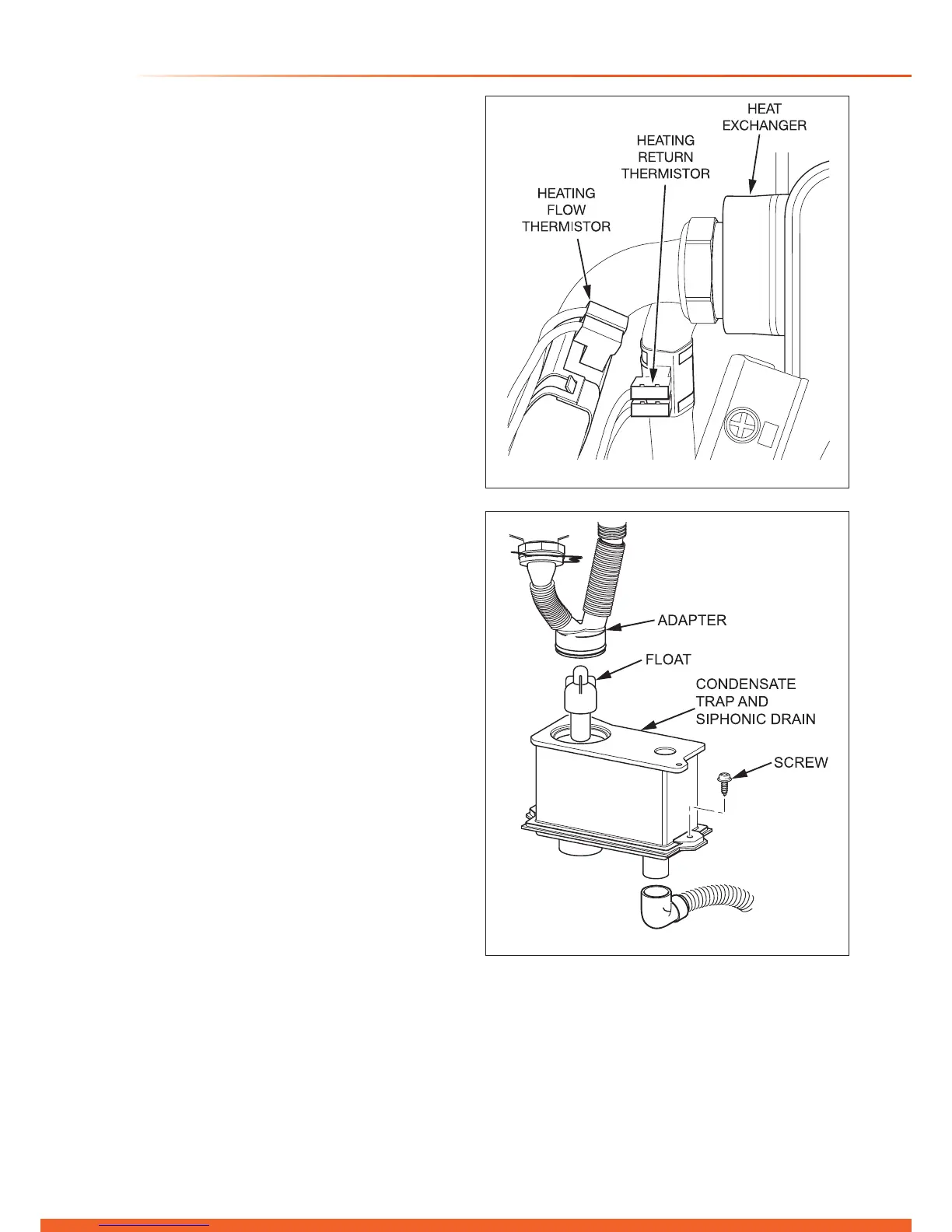
15.14 Heating Flow Thermistor
For access, refer to section 15.1.
Refer to diagram 15.10.
Remove the electrical connections from the thermistor.
Remove the retaining clip from the ow pipe.
NOTE: When reconnecting, the polarity of the wiring to
thermistors is not important.
15.15 Heating Return Thermistor
For access, refer to section 15.1.
Refer to diagram 15.10.
Remove the electrical connections from the thermistor.
Remove the retaining clip from the return pipe.
NOTE: When reconnecting, the polarity of the wiring to
thermistors is not important.
15.16 Condense Trap and Siphonic Drain
For access, refer to section 15.1.
Refer to diagram 15.11.
Remove the igniter unit as described in section 15.3 to
improve accessibility.
Remove the securing clip from the heat exchanger adapter,
then disconnect the adapter and exible hose.
Lift the siphon adapter and hose out of the condensate trap
and siphonic drain, do not disconnect the hose.
Disconnect the drain connection.
Slacken to disengage but do not remove the two securing
screws.
The condense trap will contain water, lift taking care not to
spill the water.
After replacement and before tting the adapter ll the trap
with water.
Cleaning
Remove the condense trap as previously described.
Remove the oat to clean it.
Remove any solids found.
Flush water through the trap to remove any remaining solids.
Check for any debris in the outlet hose of the condensate
drain and clean as necessary.
Diagram 15.10
13316
15 Replacement of Parts
Diagram 15.11
13544

 Loading...


