3. MACHINE RUNNING PROCEDURES ORDER
• Be sure that the machine is assembled in conformance with the Machine Assembly procedures.
• If there is any object on the machine (including the bending apparatus) they must be removed.
• LEFT-RIGHT switch on the control panel of the machine is turned to LEFT or RIGHT position,
MAN AUTO switch is turned to MAN position and machine turning direction is confirmed by
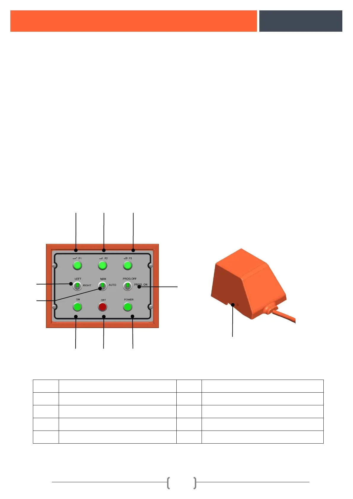
pressing on the foot pedal.
Explanation: Rotation direction is approved by taking the front of the machine as reference (Control
pane side) the clockwise as right and counter-clockwise as left. If the machine is rotating reverse of the
switch it means phases of the electricity supply are feeding reversely. This situation doesn't affect the
running system of the machine. In such case LEFT-RIGHT switch might be turned to the other side or
competent electricians might change the directions of the phases.
After fixing the direction of rotation bending adjustments should start.
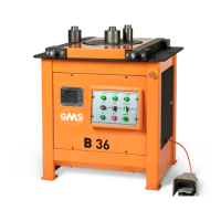
Control buttons
Figure 3: Control buttons