Positive
Terminal)
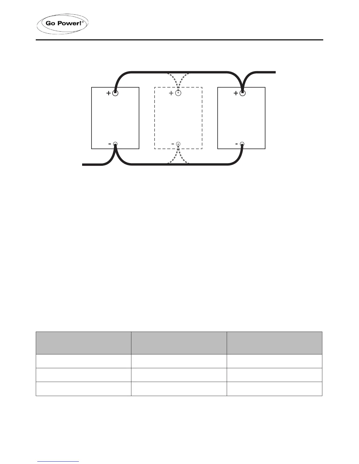
12 V
Lead-acid
Battery
To increase
capacity,
connect
additional
12 V
Lead-acid
batteries
INSTALLATION
4.7 DC WIRING SIZING
The distance between the battery bank and the Inverter should be as short as possible to
achieve maximum efciency and to reduce re hazards. The gauge of the cable should be
sized appropriately to limit the voltage drop to less than 2% when carrying the maximum input
current to prevent frequent low-input voltage warnings and shutdown. Only use high quality
copper wire.
The cables should be as short as possible and the overall length of both cables added together
should be less than 10 ft (3 m) to comply with code requirements. Keeping your wire runs as
short as possible helps to prevent: low voltage shutdowns and nuisance tripping of the DC
breaker because of increased current draw. The table below shows the recommended DC
cable size, fuses/circuit breakers and DC grounding cable sizes for the Inverter (note: these
values are correct for cables in free air, not conduit).
Model Wire AWG Inline Fuse / Circuit Breaker
GP-1750HD #2 F-200
GP-3000HD 4/0 F-400
GP-5000HD 4/0 F-400
 Loading...