EasyManua.ls Logo

Go Power GP-PWM-30-UL User Manual

Go Power GP-PWM-30-UL
34 pages
To Next Page IconTo Next Page
To Previous Page IconTo Previous Page
Page #11 background image
GP-PWM-30-UL
_________________________________________________________________________________
11
© 2018 GoPower!
Ne dépassez
pas la tension
nominale
maximum du
GP-PWM-30-UL
La tension maximum des panneaux est la
somme des courants de court-circuit (Isc) des
modules PV connectés en parallèle, multipliée
par 1,25 (ou par une valeur de l’article 690.7
du Code National Électrique fournie dans le
tableau 690.7 A). La tension qui en résulte ne
doit pas excéder 35 V. Si votre système
solaire dépasse cette valeur, veuillez
contacter votre revendeur pour obtenir un
régulateur plus approprié.
3. Select wire type and gauge. If this GP-PWM-30-UL was
purchased as part of a Go Power! Solar Power Kit, appropriate
wire type, gauge and length is provided. Please continue to
Section 6, “Operating Instructions.” If the GP-PWM-30-UL was
purchased separately, follow the instructions included here.
Wire type is recommended to be a stranded copper UV resistant wire.
Wire fatigue and the likelihood of a loose connection are greatly reduced
in stranded wire compared to solid wire. Wire gauge should be able to
sustain rated current as well as minimize voltage drop.
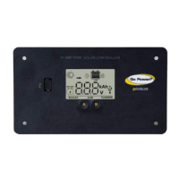
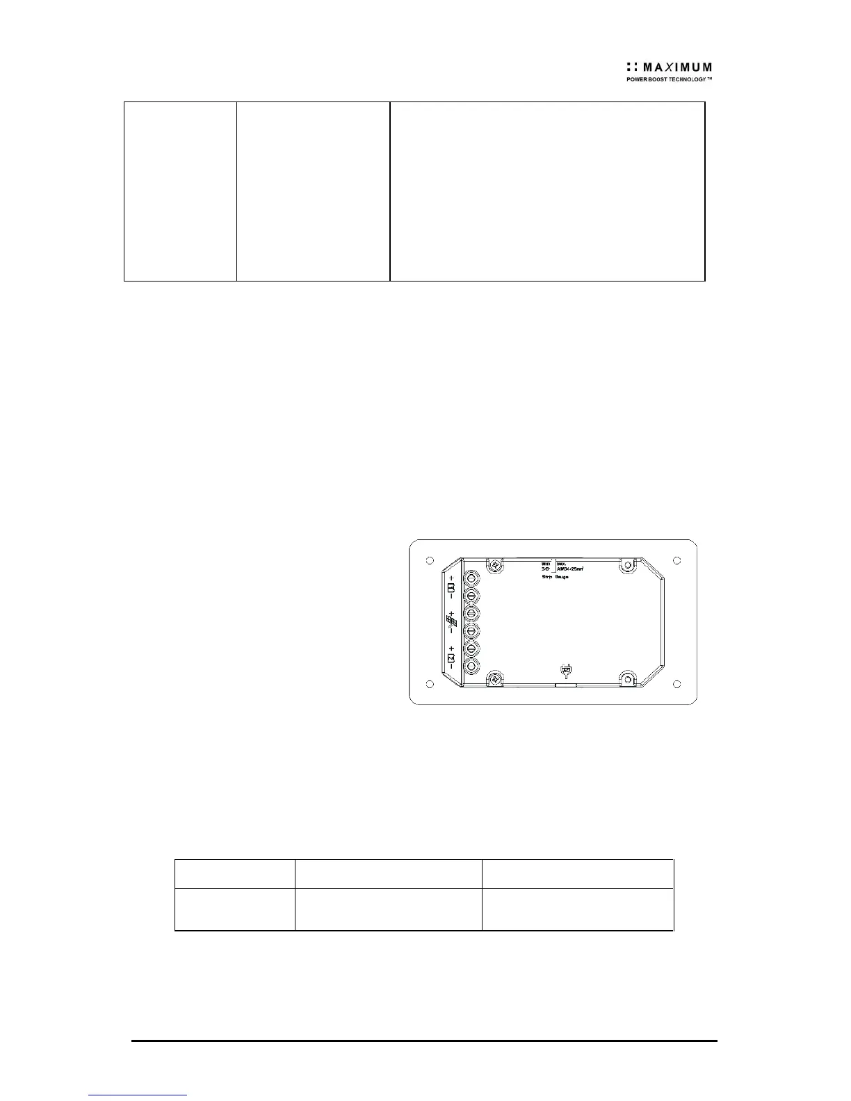
Wire Strip Gauge
You will find a strip gauge
diagram on the back of the GP-
PWM-30-UL, which helps you to
strip your wires to the correct
length. Insert wire into the
concave slot of the strip gauge
until it meets the back of the
Strip Gauge slot. Mark the
length of wire from the back of
the Strip Gauge slot to the edge of the controller with a pen or your finger
and strip all wires to be connected to the controller to this length.
Suggested Minimum Wire Gauge
(Cable length 25 ft. max. from solar array to battery bank)
Wire Type
Wire size min (AWG)
Wire size Max (AWG)
Copper Only
90°C
AWG 10
AWG 4
IMPORTANT: Identify the polarity (positive and negative) on the cable
used for the battery and solar module. Use colored wires or mark the
Question and Answer IconNeed help?

Do you have a question about the Go Power GP-PWM-30-UL and is the answer not in the manual?

Go Power GP-PWM-30-UL Specifications

General IconGeneral
TypePWM
ModelGP-PWM-30-UL
Rated Current30A
Max. Solar Array Open Circuit Voltage50V
Self Consumption< 10mA
Nominal System Voltage12V/24V
Operating Temperature-31°F ~ 149°F (-35°C ~ +65°C)
Storage Temperature-40°C to +80°C
Battery TypesAGM, GEL, Flooded, Lithium
Protection FeaturesReverse Polarity, Overload, Short Circuit
CertificationUL 1741

Summary

Installation Overview and Specifications

Introduction to Solar Controllers

Defines a solar controller and its role in a photovoltaic system.

System Voltage and Current Ratings

Specifies the system voltage and current ratings for the GP-PWM-30-UL controller.

Compatible Battery Types

Lists the types of lead-acid batteries compatible with the GP-PWM-30-UL.

Low Voltage Disconnect for USB Port

Details the automatic USB port shutdown when battery voltage is low.

Regulatory Compliance Information

Presents regulatory compliance information such as CE and RoHS certifications.

GP-PWM-30-UL Technical Specifications

Provides detailed technical specifications for the GP-PWM-30-UL controller.

Important Safety Instructions

Power Source and Battery Handling Safety

Advises on disconnecting power sources and safe battery handling practices.

Wiring Connection and Polarity Precautions

Emphasizes secure connections and correct polarity to prevent damage.

Personal Safety and Protective Gear

Recommends wearing protective gear and exercising caution during installation.

Maximum Electrical Rating Limits

Warns against exceeding the maximum current and voltage ratings of the controller.

Tools and Installation Preparation

Tools and Materials Needed for Installation

Lists the necessary tools and materials for installation.

Choosing an Optimal Installation Location

Provides guidelines for selecting an optimal location for mounting the controller.

Installation and Wiring Procedures

Controller Mounting Preparation

Instructions on preparing the mounting location using the provided template.

Completing Solar Module Installation

Guidance on completing the installation of solar modules.

Selecting Appropriate Wire Type and Gauge

Guidance on selecting appropriate wire type and gauge for connections.

Wire Stripping Gauge Utilization

Explanation of the wire strip gauge diagram for correct wire preparation.

Wiring and Terminal Torque Specifications

Detailed instructions for wiring, including torque specifications for terminals.

Controller Mounting and Battery Type Setup

Instructions for physically mounting and setting the battery type before operation.

Wiring Diagrams for Battery Configuration

Wiring Diagram: Charging a Single Battery

Wiring diagram for connecting a single battery to the controller.

Wiring Diagram: Charging Two Batteries

Wiring diagram for connecting two batteries to the controller.

Operating the GP-PWM-30-UL Controller

Controller Power Up Sequence

Steps and expected behavior when powering up the GP-PWM-30-UL controller.

Setting Battery Type and Charging Profile

Procedure for setting the battery type and charging profile for Battery 1 and Battery 2.

Battery Charging Profile Chart

Details charging parameters for different battery types (Sealed/Gel, AGM, Flooded).

Maximum Power Boost Technology Explained

Explains the Maximum Power Boost Technology feature for enhanced charging.

Viewing Controller Display Information Modes

Guides on viewing information via manual scroll and auto scroll display modes.

Understanding Error Codes and Conditions

Details error conditions like Over Voltage, Low Voltage, and Reverse Polarity.

Display Symbols and Indicators

Battery 1 Display Symbols

Lists and explains symbols related to Battery 1 status and charging.

Battery 2 Display Symbols

Lists and explains symbols related to Battery 2 status and charging.

General Controller Symbols and Indicators

Explains other general symbols displayed on the controller, including SOC.

Advanced Features and Support

Inverter Control Functionality

Instructions on connecting and controlling compatible Go Power! inverters.

USB Charging Port Operation

Details the USB charging port, its capabilities, and power source.

Troubleshooting Common Issues

Frequently Asked Questions (FAQs)

Addresses common questions regarding battery maintenance and display readings.

Display and Voltage Troubleshooting

Troubleshooting steps for display issues and inaccurate voltage readings.

Current Reading and Module Issues

Troubleshooting steps for current reading problems and solar module issues.

Warranty and Service Information

Limited Warranty Terms and Conditions

Outlines the terms and conditions of the limited warranty for the GP-PWM-30-UL.

Repair and Return Support Procedures

Information on how to get technical support and handle product returns.

Using the Installation Template Guide

Instructions on how to use the provided template for flush mounting.

Related product manuals