Do you have a question about the Go Power GP-PWM-30-UL and is the answer not in the manual?
Defines a solar controller and its role in a photovoltaic system.
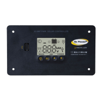
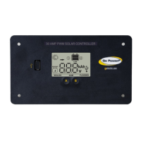
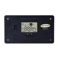
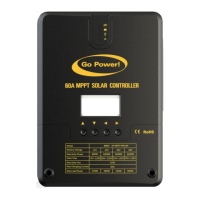
Specifies the system voltage and current ratings for the GP-PWM-30-UL controller.
Lists the types of lead-acid batteries compatible with the GP-PWM-30-UL.
Details the automatic USB port shutdown when battery voltage is low.
Presents regulatory compliance information such as CE and RoHS certifications.
Provides detailed technical specifications for the GP-PWM-30-UL controller.
Advises on disconnecting power sources and safe battery handling practices.
Emphasizes secure connections and correct polarity to prevent damage.
Recommends wearing protective gear and exercising caution during installation.
Warns against exceeding the maximum current and voltage ratings of the controller.
Lists the necessary tools and materials for installation.
Provides guidelines for selecting an optimal location for mounting the controller.
Instructions on preparing the mounting location using the provided template.
Guidance on completing the installation of solar modules.
Guidance on selecting appropriate wire type and gauge for connections.
Explanation of the wire strip gauge diagram for correct wire preparation.
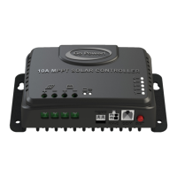
Detailed instructions for wiring, including torque specifications for terminals.
Instructions for physically mounting and setting the battery type before operation.
Wiring diagram for connecting a single battery to the controller.
Wiring diagram for connecting two batteries to the controller.
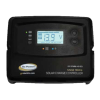
Steps and expected behavior when powering up the GP-PWM-30-UL controller.
Procedure for setting the battery type and charging profile for Battery 1 and Battery 2.
Details charging parameters for different battery types (Sealed/Gel, AGM, Flooded).
Explains the Maximum Power Boost Technology feature for enhanced charging.
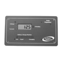
Guides on viewing information via manual scroll and auto scroll display modes.
Details error conditions like Over Voltage, Low Voltage, and Reverse Polarity.
Lists and explains symbols related to Battery 1 status and charging.
Lists and explains symbols related to Battery 2 status and charging.
Explains other general symbols displayed on the controller, including SOC.
Instructions on connecting and controlling compatible Go Power! inverters.
Details the USB charging port, its capabilities, and power source.
Addresses common questions regarding battery maintenance and display readings.
Troubleshooting steps for display issues and inaccurate voltage readings.
Troubleshooting steps for current reading problems and solar module issues.
Outlines the terms and conditions of the limited warranty for the GP-PWM-30-UL.
Information on how to get technical support and handle product returns.
Instructions on how to use the provided template for flush mounting.
| Type | PWM |
|---|---|
| Model | GP-PWM-30-UL |
| Rated Current | 30A |
| Max. Solar Array Open Circuit Voltage | 50V |
| Self Consumption | < 10mA |
| Nominal System Voltage | 12V/24V |
| Operating Temperature | -31°F ~ 149°F (-35°C ~ +65°C) |
| Storage Temperature | -40°C to +80°C |
| Battery Types | AGM, GEL, Flooded, Lithium |
| Protection Features | Reverse Polarity, Overload, Short Circuit |
| Certification | UL 1741 |