GP-PWM-30-UL
_________________________________________________________________________________
20
© 2018 GoPower!
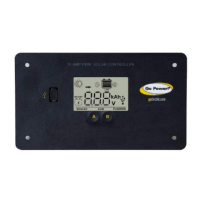
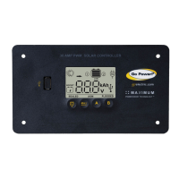
Icons Displayed: Arrow, Ampere Symbol, Battery SOC, Symbol 2
The battery state of charge
is shown as a percentage.
Icons Displayed: Battery
SOC, Percent Symbol (%),
Symbol 2
Mode 2: Automatically Change Display Information
You can select the auto mode by holding down the A Button for 3
seconds.
The display shows the same information as in Mode 1 but changes the
display automatically every 8 seconds between following information:
Battery 1: Voltage; PV Charging Current; Battery State of Charge (SOC)
Battery 2: Voltage; PV Charging Current; Battery State of Charge (SOC)
If Battery 2 is not connected, the Controller changes only the
information for Battery 1.
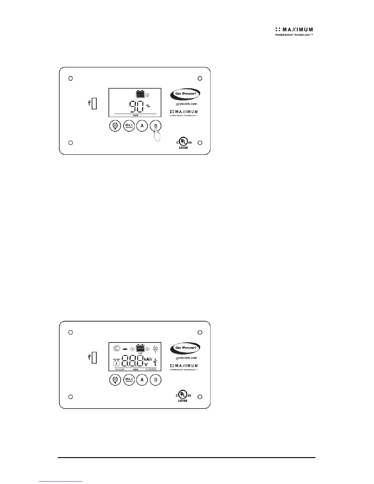
7.6 Errors
Over Voltage
If the GP-PWM-30-UL
experiences a battery over
voltage (15.5 VDC) on
battery bank 1, the
controller will stop
operating, and the display
will begin to flash with all
icons. The controller will
resume operating when the
voltage drops to a normal
level <15.5 VDC.
Icons Displayed: All symbols
 Loading...