Compass™ Service Manual
GP600-SM 9 RevA02062006
I. Removing and Installing
the Retractable Desk Arm
Assembly
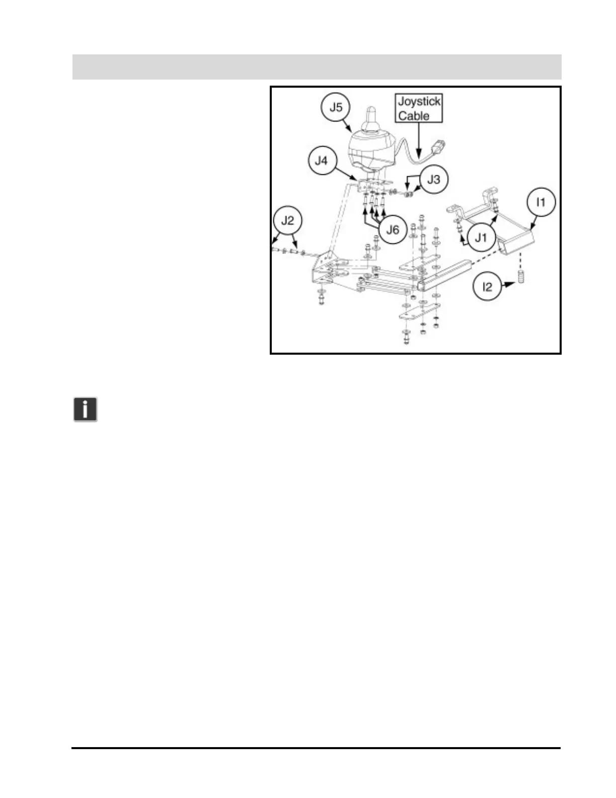
1. Remove the retractable desk arm
assembly from the receiver bracket
(I1) by loosening the 4-mm
setscrew (I2). See figure 8.
2. Reverse these instructions to
reinstall the retractable desk arm
assembly.
J. Moving the Joystick to
the Left Side of the Power
Chair
1. Remove the right retractable desk
arm assembly. Refer to instruction
set I.
Note: You will need to
order a left retractable desk
arm assembly to complete this installation.
2. Remove the receiver bracket (I1) from under the right armrest by uninstalling the two Allen-head screws
and 5-mm lock washers (J1). See figure 8.
3. Reinstall the armrest receiver bracket (I1) to left armrest assembly.
4. Remove the two 3-mm button-head screws (J2) and 5/16-in. nuts (J3) from the joystick mounting plate
(J4).
5. Remove the joystick (J5) from the joystick mounting plate by uninstalling the 4-mm Allen-head screws
(J6) underneath the plate.
6. Attach the joystick to the new left retractable desk arm assembly, following steps 5 and 4 in reverse, with
the same hardware.
7. Reattach the retractable desk arm assembly to the armrest receiver bracket, connecting the additional
12-in. length of harness to the joystick cable and current jumper harness to compensate for the extra dis-
tance.
K. Installing the Seatbelt
1. Remove the armrest adjustment knobs at the rear of the power chair.
2. Insert the knob stem through the hole at the end of each seatbelt, and reinstall the knobs.
Figure 8. Retractable Desk Arm Assembly (Note: Entire assembly
broken down for clarification. Only remove/install parts labeled with
callouts.)