Compass™ Service Manual
GP600-SM 6 RevA 02062006
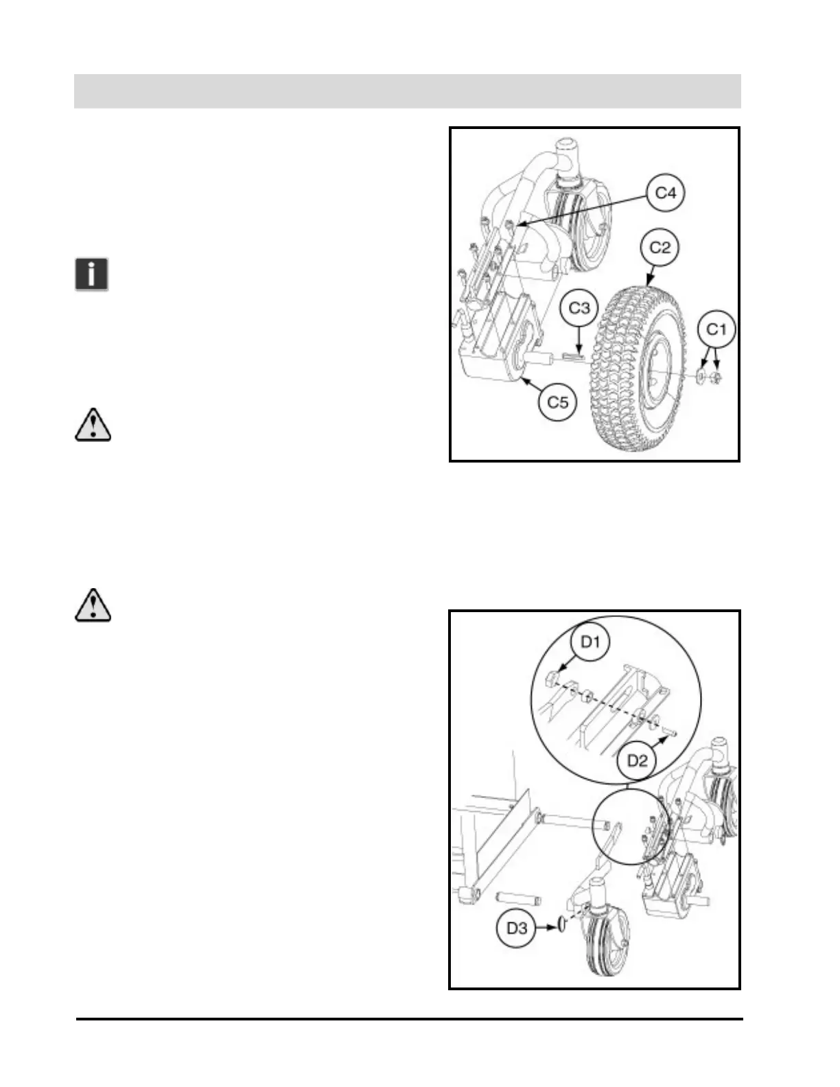
C. Changing a Drive Wheel and Motor
1. Lock (engage) the motors.
2. Place the power chair on its side, being careful to
protect its surface.
Note: Performing the removals in instruc-
tion set A is not necessary, but makes wheel
and motor removal easier.
3. Remove the center nut and washer (C1) on the
wheel hub, using a 17-mm deep-dish socket wrench,
and pull off the drive wheel assembly (C2). See
figure 2.
WARNING: DO NOT REMOVE THE
FOUR ACORN NUTS FROM THE HUB.
4. Remove the key (C3) from the keyway in the
transaxle.
5. Remove the six 5-mm Allen-head bolts (C4) that secure the transaxle assembly to the power chair frame.
6. Remove the motor (C5). Reverse these instructions to reinstall the motor and drive wheel.
WARNING: REMEMBER TO REIN-
STALL THE KEY IN THE TRANSAXLE.
D. Removing and Installing the Front
Caster Arm
1. Remove the front caster arm cover, rear fender, and
drive wheel. Refer to instruction sets B and C.
2. Remove the 17-mm nut (D1) and corresponding
Phillips-head screw (D2) that hold the front caster
arm to the rear caster area. See figure 3.
3. Remove the snap ring (D3) from the lower front frame
assembly.
4. Slide the front caster arm out and off of the front frame.
Reverse these instructions to reinstall the front caster
arm.
Figure 2. Left Drive Wheel and Motor
Figure 3. Left Front Caster