5
Avoid dusty or smoky environments or locations near sources of heat.
For proper installation, use the template supplied with the product.
1. Position the top of the template at a height of 1.65m.
2. If you are going to use an embedding box to pass the wiring through, make sure that it is in line with the holes
corresponding to the box model chosen and fix the connector. If you prefer to fix the connector directly to the
wall, make four 6mm holes at the points indicated (A), insert the wall plugs supplied and screw in the connector.
3. Pass the installation wires through the middle hole and connect them to the removable terminals as shown in the
wiring diagrams. Before connecting the removable terminals to the monitor, configure the switch as indicated below.
4. Connect the removable terminals to the monitor and place the monitor in front of the connector, making sure the
fixings line up. Move the monitor downwards to secure it.
INSTALLATION
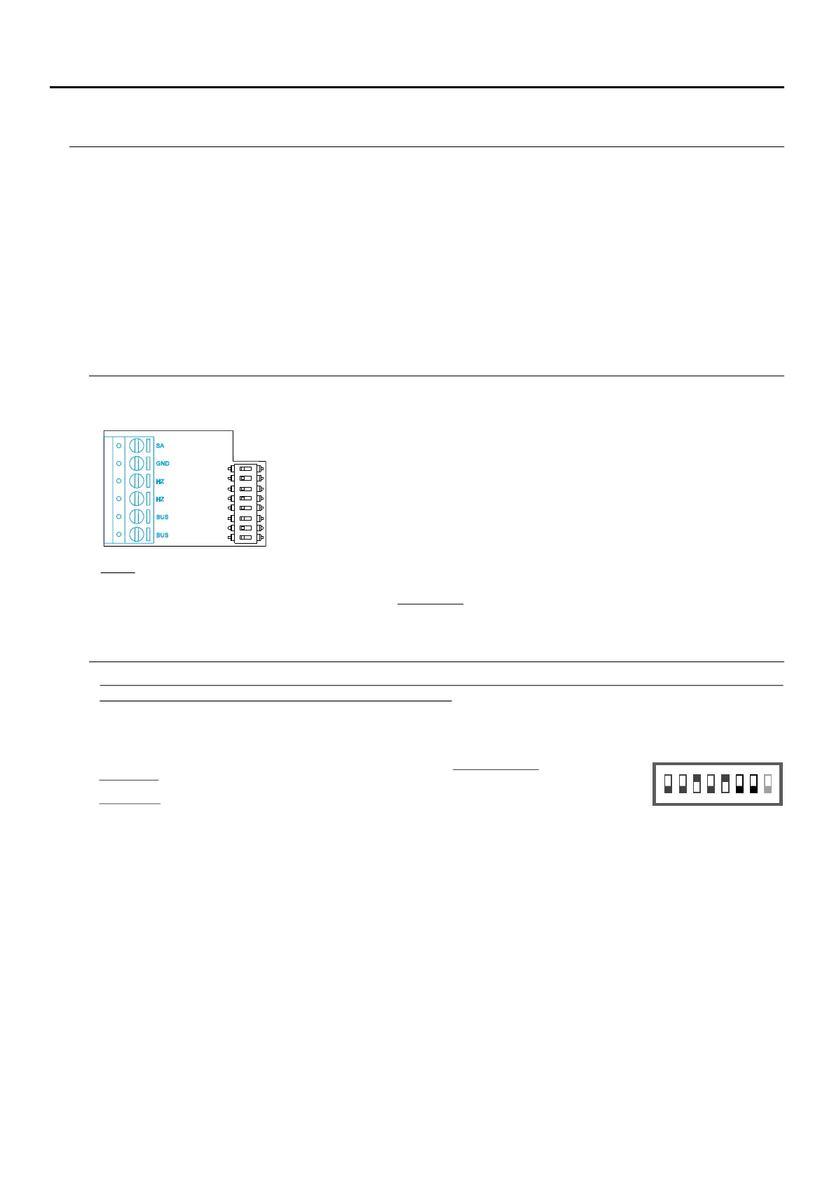
INSTALLATION TERMINALS ( )L
For ease of installation, the installation terminals are removable and supplied in a separate bag. Once the
terminals are wired, place them in position.
BUS, BUS: Communication BUS (non-polarised).
SA, GND:Auxiliary call repeater output (max 50mA/12V), relay SAR-12/24.
HZ, HZ: Apartment front door button input:
Connect only on the master monitor. The signal received is then transmitted
to the slave monitors in the same apartment through the BUS.
CONFIGURATION SWITCHES ( )K
Note: HZ push button function mode: When HZ push button is pressed will be call tone and activate the output of
auxiliary call repeater with standby monitor, call process, communication process (HZ tone with lower audio level),
intercom process and "Do not disturb" mode. Important: Up to 6 monitors/ apartments with push button "HZ"
activated at the same time (with system and monitors in standby).
ART4 LITE G2+ / ART 4H LITE G2+ monitor with V.04 & later, ART 4B LITE G2+ with V.05 & later and ART
4TH G2+ monitor with V.01 & later (addresses 1 to 128):
Switches to 71 : Sets the monitor address (addresses 1 2 ).to 1 8
The switches set to OFF have a zero value. The values of the switches set to ON are shown in the table below. The
monitor code is the sum of the values of the switches set to ON.
.
Switch 8: This activates the end-of-line resistance in the ON position. Activate it in monitors where the bus cable
ends. Deactivate it only in intermediate monitors.
.
To define whether the monitor is master or slave:
To define whether the monitor is master or slave (see special codes page 23 to 26). Each apartment must have one
master monitor, and only one.
.
Important: V.04This manual describes new menu (with white background) only with and later of ART 4 LITE G2+,
ART 4H LITE G2+ monitors, and later of ART 4B LITE G2+ monitors and with and later of ART 4TH LITEV.05 V.01
G2+ monitor.
ART 4 LITE G2+, ART 4H LITE G2+ monitors with and earlier refer to the quick guide enclosed with theV.03
corresponding monitor.
Important: Apartment 1 (Dip1 to ON & Dip2-Dip to OFF)7
Important: Apartment 128 (Dip1 - Dip7 to OFF).
Switch number 6 7: 1 2 3 4 5
: 1 2 4 8 16Value when ON 32 64
Table of values
1 2 3
ON
E mpl : 0xa e 0+0+ 0+4+0+16+ = 20
4 5 6 7 8
SA
GND
HZ
HZ
ON
1 2 3 4 5 6 7
8
BUS
BUS
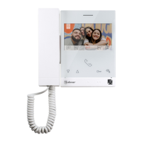
ART /G2+4 MONITORLITE