6
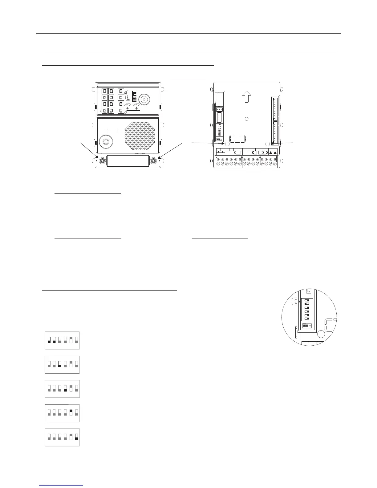
INSTALLATION OF THE DOOR PANEL
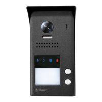
Codes assigned to the call buttons of the sound module:
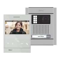
STAINLESS STEEL NEXA MODULAR GB2 VIDEO DOOR ENTRY SYSTEM KIT – HOUSES
EL632 GB2A
Co s 16 31de - Co s 0 15de -
P1P2 P2
The sound module's P1 and P2 buttons are assigned with factory codes.
- Apartment 1, button 'P1':Assigned with codes 0-15.
Monitors in this apartment must be set with codes in order of allocation from 0 to 15.
When button 'P1' on the door panel is pressed, all of the monitors in apartment 1 will receive the call and only
the monitor assigned with code 0 will show the door panel image. If the call is answered from any other
monitor in the apartment, the image on the monitor assigned with code 0 will disappear and audio and video
communication will be established with the door panel.
- Apartment 2, button 'P2':Assigned with codes 16-31 ( ).only kits with 2 buttons
Monitors in this apartment must be set with codes in order of allocation from 16 to 31.
When button 'P2' on the door panel is pressed, all of the monitors in apartment 2 will receive the call and only
the monitor assigned with code 16 will show the door panel image. If the call is answered from any other
monitor in the apartment, the image on the monitor assigned with code 0 will disappear and audio and video
communication will be established with the door panel.
Co s 16 31de -
Description of the sound module DIP switch:
The DIP switch is located on the left side of the back of the module.
1 2
3 4 5 6
ON
Door panel address:
DIP switches: 1 and 2 OFF (address 1), 1 ON and 2 OFF (address 2), 1 OFF and
2 ON (address 3), 1 and 2 ON (address 4).
1 2 4 5 6
3
ON
Leave in the OFF position.
1 2 3 5 6
4
ON
Leave in the OFF position for use with door panels in houses and set to ON for
use in apartment buildings.
1 2 3 4 6
5
ON
Leave in the ON position to set the door opening time to 5 seconds. Set to OFF
to set the door opening time to 1 second.
1 2 3 4 5
6
ON
Set to ON to configure: (see pp. 8-9)
Vocal synthesis language, vocal synthesis volume, relay 1 and relay 2 of the lock
release is NO or NC Leave in the OFF position once configuration is complete.
*
( )
*
( )
Factory setting.
*
( )
*
( )
*
( )
*
( )
*
( )
1 2 3 4 5 6
ON
NA2
+
AP-
C1
NA1
AP+
C2
AP+ AP-
P1 P2
BUSBUS
Relay 2
Relay 1
_
12Vdc
1
2