24 25
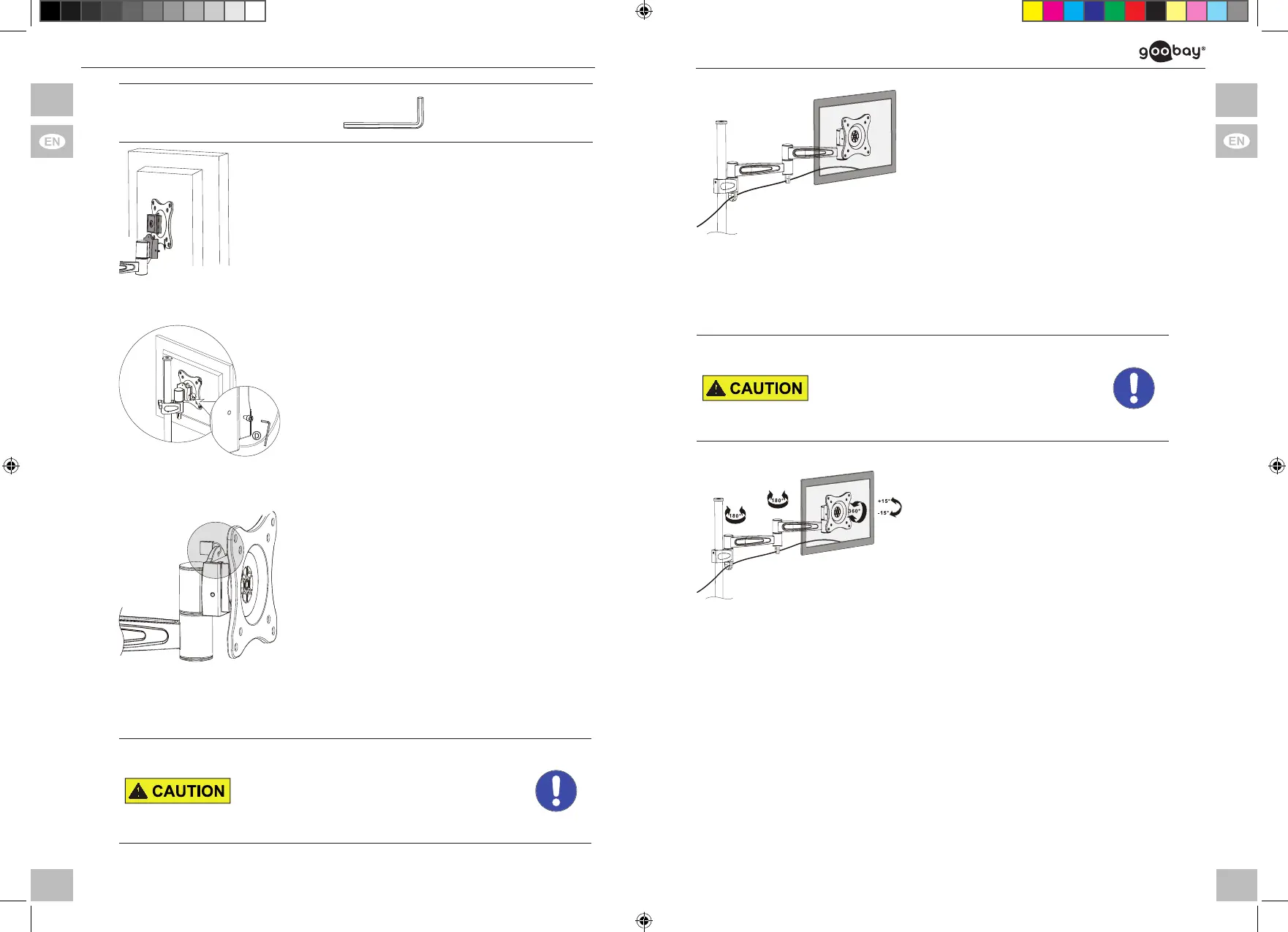
Allen key 3mm D
1. AttachVESAPlatewithatscreen
together with a second person to the
pole assembly (A).
Fig . 18: Attaching the at screen
2. Fixtheatscreenbytightenthe
locking screw clockwise.
Fig. 19: Fixing the at screen
3. Locktheatscreenwithapadlock,if
necessary.
Fig. 20: Locking the at screen
4.6 Laying the cables
Risk of injury by moving product parts
>>
>>
Do not hold limbs between shear parts
during use.
Mind the mobility of the product during
use. This may move away from the wall
or towards it and swivel sideways.
Ta b . 2 0: Laying the cables
1. Selectsufcientlylongcables
to ensure the mobility of the
atscreen.
2. Pin the cables into the cable
guides as shown.
Fi g . 21: Laying the cables
End of installing. To remove, proceed in reversed order.
5 Aligningtheatscreen
Risk of injury by moving product parts
>>
>>
Do not hold limbs between shear parts
during use.
Mind the mobility of the product during
use. This may move away from the wall
or towards it and swivel sideways.
Ta b . 2 1: Aligning the at screen
Aligntheatscreenasneeded
>> Vertically,
>> Horizontally and / or
>> From the axis of rotation.
Fig. 2 2: Aligning the at screen
6 Warranty and Liability
• The producer grants a 2 years warranty to a new device.
• Asthemanufacturerhasnoinuenceoninstallation,warrantyonlyapplies
to the product itself.
• If any fault or damage is detected on your device, please contact your dealer
and provide your sales slip or invoice as evidence of the purchase, if
necessary. Your dealer will repair the fault either on site, or send the device
to the manufacturer. You make the work of our technicians considerably
easier, describing possible faults in detail – only then you can be assured
thatfaults,occurringonlyrarely,willbefoundandrepairedwithcertainty!
• The manufacturer is not liable for damages to persons or property caused by
63496+63497_manual_V4.indd 24-25 28.05.2018 16:02:53