Performance Test
Copyright © 2020 Shenzhen Goodix Technology Co., Ltd. 13
10 Performance Test
10.1 RF Test
The GR5515 SK Board reserves a small RF connector (J50), which can be connected to a spectrum analyzer or a
Bluetooth LE tester (for example, TLF3000) to test the RF performance of the GR5515 SK Board.
The RF connector, J50, integrates an internal switch:
• By default, if no test line probe is connected to J50, the RF circuit signal is connected to on-board antenna.
• If any test line probe is connected to J50, the RF circuit signal is directly connected with the test line, not the
board-level antenna any more. The other end of the test line is connected to a test instrument through a
standard SMA connector.
Note:
It is recommended to use a high-frequency test line, such as MURATA MXHS83QE3000, to test RF performance for
the GR5515 SK Board; the test probe is not included in the GR5515 SK package.
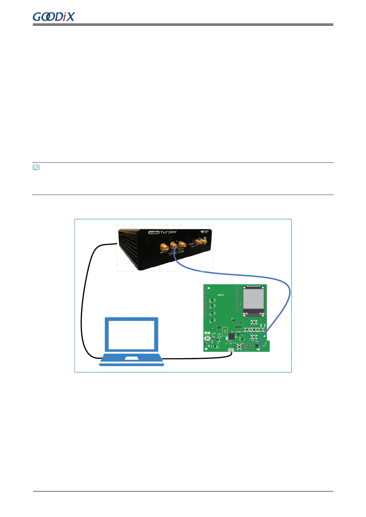
Figure 10-1 shows test connection between a GR5515 SK Board and TLF3000 by taking TLF3000 as an example.
Micro USB Cable
Micro USB Cable
Cable
Back
Figure 10-1 Connection between GR5515 SK Board and TLF3000
After establishing connection, you can select different test items from the software on the PC, to test RF-related
parameters.