EasyManua.ls Logo

Goodman AM9S80 - Page 6

Goodman AM9S80
55 pages
Print Icon
To Next Page IconTo Next Page
To Previous Page IconTo Previous Page
Loading...
SYSTEM OPERATION
6
applicable codes. The furnace must be electrically grounded
in accordance with local codes or, in their absence, with the
latest edition of The National Electric Code, ANSI NFPA 70
and/or The Canadian Electric Code CSA C22.1. An electri-
cal disconnect must be provided at the furnace location.
ξ˜±ξ˜²ξ˜·ξ˜¨ξ˜ξ˜ƒ ξ˜―ξ™Œξ™‘ξ™ˆξ˜ƒ ξ™“ξ™’ξ™ξ™„ξ™•ξ™Œξ™—ξ™œξ˜ƒ ξ™ξ™˜ξ™–ξ™—ξ˜ƒ ξ™…ξ™ˆξ˜ƒ ξ™’ξ™…ξ™–ξ™ˆξ™•ξ™™ξ™ˆξ™‡ξ˜ƒ ξ™šξ™‹ξ™ˆξ™‘ξ˜ƒξ™ξ™„ξ™Žξ™Œξ™‘ξ™Šξ˜ƒξšΏξ™ˆξ™ξ™‡ξ˜ƒ
connections.
Connect hot, neutral, and ground wires as shown in the wir-
ing diagram located on the unit’s blower door. Metal conduit
is not considered a substitute for an actual ground wire to
ξ™—ξ™‹ξ™ˆξ˜ƒξ™˜ξ™‘ξ™Œξ™—ξ˜‘ξ˜ƒξ˜―ξ™Œξ™‘ξ™ˆξ˜ƒξ™“ξ™’ξ™ξ™„ξ™•ξ™Œξ™—ξ™œξ˜ƒξ™ξ™˜ξ™–ξ™—ξ˜ƒξ™…ξ™ˆξ˜ƒξ™’ξ™…ξ™–ξ™ˆξ™•ξ™™ξ™ˆξ™‡ξ˜ƒξ™šξ™‹ξ™ˆξ™‘ξ˜ƒξ™ξ™„ξ™Žξ™Œξ™‘ξ™Šξ˜ƒξšΏξ™ˆξ™ξ™‡ξ˜ƒ
connections. Line voltage connections can be made through
either the right or left side panel.
ξ˜·ξ™‹ξ™ˆξ˜ƒξ™‰ξ™˜ξ™•ξ™‘ξ™„ξ™†ξ™ˆξ˜ƒξ™Œξ™–ξ˜ƒξ™–ξ™‹ξ™Œξ™“ξ™“ξ™ˆξ™‡ξ˜ƒξ™†ξ™’ξ™‘ξšΏξ™Šξ™˜ξ™•ξ™ˆξ™‡ξ˜ƒξ™‰ξ™’ξ™•ξ˜ƒξ™„ξ˜ƒξ™•ξ™Œξ™Šξ™‹ξ™—ξ˜ƒξ™–ξ™Œξ™‡ξ™ˆξ˜ƒξ˜‹ξ™ξ™ˆξ™‰ξ™—ξ˜ƒξ™–ξ™Œξ™‡ξ™ˆξ˜ƒ
ξ™‰ξ™’ξ™•ξ˜ƒξ™†ξ™’ξ™˜ξ™‘ξ™—ξ™ˆξ™•ξ›€ξ™’ξ™šξ˜Œξ˜ƒξ™ˆξ™ξ™ˆξ™†ξ™—ξ™•ξ™Œξ™†ξ™„ξ™ξ˜ƒξ™†ξ™’ξ™‘ξ™‘ξ™ˆξ™†ξ™—ξ™Œξ™’ξ™‘ξ˜ƒξ™šξ™Œξ™—ξ™‹ξ˜ƒξ™—ξ™‹ξ™ˆξ˜ƒξ™ξ™˜ξ™‘ξ™†ξ™—ξ™Œξ™’ξ™‘ξ˜ƒξ™…ξ™’ξ™›ξ˜ƒ
located inside the burner compartment. To make electrical
connections through the opposite side of the furnace, the
ξ™ξ™˜ξ™‘ξ™†ξ™—ξ™Œξ™’ξ™‘ξ˜ƒξ™…ξ™’ξ™›ξ˜ƒξ™ξ™˜ξ™–ξ™—ξ˜ƒξ™…ξ™ˆξ˜ƒξ™•ξ™ˆξ™ξ™’ξ™†ξ™„ξ™—ξ™ˆξ™‡ξ˜ƒξ™—ξ™’ξ˜ƒξ™—ξ™‹ξ™ˆξ˜ƒξ™’ξ™—ξ™‹ξ™ˆξ™•ξ˜ƒξ™–ξ™Œξ™‡ξ™ˆξ˜ƒξ™’ξ™‰ξ˜ƒξ™—ξ™‹ξ™ˆξ˜ƒξ™…ξ™˜ξ™•ξ™‘-
er compartment prior to making electrical connections.

ξ˜¨οŽŒοŽοŽοŽ›ξ˜ƒοŽ—οŽŽξ˜ƒοŽ›οŽοŽοŽοŽœξ˜ƒοŽ•οŽοŽœοŽ‰οŽ”ξ˜ƒοŽοŽ—οŽ”οŽοŽ›ξ˜ƒοŽ•οŽ‰οŽ‘ξ˜ƒοŽŠοŽξ˜ƒοŽ›οŽοŽ‰οŽšοŽ˜ξ˜‘ξ˜ƒξ˜ΈοŽ›οŽξ˜ƒοŽοŽ”οŽ—οŽžοŽοŽ›ξ˜ƒοŽ‰οŽ›ξ˜ƒοŽ‰ξ˜ƒ
οŽ˜οŽšοŽοŽ‹οŽ‰οŽοŽœοŽ‘οŽ—οŽ–ξ˜ƒοŽŸοŽοŽοŽ–ξ˜ƒοŽšοŽοŽ•οŽ—οŽžοŽ‘οŽ–οŽξ˜ƒοŽοŽ—οŽ”οŽξ˜ƒοŽ˜οŽ”οŽοŽοŽ›ξ˜‘
 Wire routing must not interfere with circulator blower
ξ™’ξ™“ξ™ˆξ™•ξ™„ξ™—ξ™Œξ™’ξ™‘ξ˜ξ˜ƒξšΏξ™ξ™—ξ™ˆξ™•ξ˜ƒξ™•ξ™ˆξ™ξ™’ξ™™ξ™„ξ™ξ˜ξ˜ƒξ™’ξ™•ξ˜ƒξ™•ξ™’ξ™˜ξ™—ξ™Œξ™‘ξ™ˆξ˜ƒξ™ξ™„ξ™Œξ™‘ξ™—ξ™ˆξ™‘ξ™„ξ™‘ξ™†ξ™ˆξ˜‘
ξ˜ͺ
ξ˜·οŽ—ξ˜ƒοŽ‰οŽžοŽ—οŽ‘οŽŒξ˜ƒοŽœοŽοŽξ˜ƒοŽšοŽ‘οŽ›οŽ“ξ˜ƒοŽ—οŽŽξ˜ƒοŽοŽ”οŽοŽ‹οŽœοŽšοŽ‘οŽ‹οŽ‰οŽ”ξ˜ƒοŽ›οŽοŽ—οŽ‹οŽ“ξ˜ξ˜ƒοŽ‘οŽ–οŽ’οŽοŽšοŽ‘ξ˜ξ˜ƒοŽ—οŽšξ˜ƒοŽŒοŽοŽ‰οŽœοŽξ˜ξ˜ƒοŽœοŽοŽξ˜ƒ
οŽŽοŽοŽšοŽ–οŽ‰οŽ‹οŽξ˜ƒοŽ•οŽοŽ›οŽœξ˜ƒοŽŠοŽξ˜ƒοŽοŽ”οŽοŽ‹οŽœοŽšοŽ‘οŽ‹οŽ‰οŽ”οŽ”οŽ‘ξ˜ƒοŽοŽšοŽ—οŽοŽ–οŽŒοŽοŽŒξ˜ƒοŽ‘οŽ–ξ˜ƒοŽ‰οŽ‹οŽ‹οŽ—οŽšοŽŒοŽ‰οŽ–οŽ‹οŽξ˜ƒοŽŸοŽ‘οŽœοŽξ˜ƒ
οŽ”οŽ—οŽ‹οŽ‰οŽ”ξ˜ƒοŽ‹οŽ—οŽŒοŽοŽ›ξ˜ƒοŽ—οŽšξ˜ξ˜ƒοŽ‘οŽ–ξ˜ƒοŽœοŽοŽοŽ‘οŽšξ˜ƒοŽ‰οŽŠοŽ›οŽοŽ–οŽ‹οŽξ˜ξ˜ƒοŽŸοŽ‘οŽœοŽξ˜ƒοŽœοŽοŽξ˜ƒοŽ”οŽ‰οŽœοŽοŽ›οŽœξ˜ƒοŽοŽŒοŽ‘οŽœοŽ‘οŽ—οŽ–ξ˜ƒοŽ—οŽŽξ˜ƒ
οŽœοŽοŽξ˜ƒξ˜±οŽ‰οŽœοŽ‘οŽ—οŽ–οŽ‰οŽ”ξ˜ƒξ˜¨οŽ”οŽοŽ‹οŽœοŽšοŽ‘οŽ‹ξ˜ƒξ˜¦οŽ—οŽŒοŽξ˜‘
ξ˜”ξ˜”ξ˜˜ξ˜ƒξ˜ΉοŽ—οŽ”οŽœξ˜ƒξ˜―οŽ‘οŽ–οŽξ˜ƒξ˜¦οŽ—οŽ–οŽ–οŽοŽ‹οŽœοŽ‘οŽ—οŽ–ξ˜ƒοŽ—οŽŽξ˜ƒξ˜€οŽ‹οŽ‹οŽοŽ›οŽ›οŽ—οŽšοŽ‘οŽοŽ›ξ˜ƒ
ξ˜‹ξ˜¨οŽ”οŽοŽ‹οŽœοŽšοŽ—οŽ–οŽ‘οŽ‹ξ˜ƒξ˜€οŽ‘οŽšξ˜ƒξ˜¦οŽ”οŽοŽ‰οŽ–οŽοŽšξ˜Œ
ξ˜ͺ
ξ˜ͺξ˜«ξ˜ƒξ˜Ήξ˜²ξ˜―ξ˜·ξ˜€ξ˜ͺ
ξ˜§οŽ‘οŽ›οŽ‹οŽ—οŽ–οŽ–οŽοŽ‹οŽœξ˜ƒξ˜€ξ˜―ξ˜―ξ˜ƒοŽ˜οŽ—οŽŸοŽοŽšξ˜ƒοŽŠοŽοŽŽοŽ—οŽšοŽξ˜ƒοŽ›οŽοŽšοŽžοŽ‘οŽ‹οŽ‘οŽ–οŽξ˜ƒοŽ—οŽšξ˜ƒ
οŽ‹οŽοŽ‰οŽ–οŽοŽ‘οŽ–οŽξ˜ƒοŽ‰οŽ–οŽ‘ξ˜ƒοŽοŽ”οŽοŽ‹οŽœοŽšοŽ‘οŽ‹οŽ‰οŽ”ξ˜ƒοŽŸοŽ‘οŽšοŽ‘οŽ–οŽξ˜‘ξ˜ƒξ˜°οŽοŽ”οŽœοŽ‘οŽ˜οŽ”οŽξ˜ƒοŽ˜οŽ—οŽŸ-
οŽοŽšξ˜ƒοŽ›οŽ—οŽοŽšοŽ‹οŽοŽ›ξ˜ƒοŽ•οŽ‰οŽ‘ξ˜ƒοŽŠοŽξ˜ƒοŽ˜οŽšοŽοŽ›οŽοŽ–οŽœξ˜‘ξ˜ƒξ˜©οŽ‰οŽ‘οŽ”οŽοŽšοŽξ˜ƒοŽœοŽ—ξ˜ƒοŽŒοŽ—ξ˜ƒοŽ›οŽ—ξ˜ƒ
οŽ•οŽ‰οŽ‘ξ˜ƒοŽ‹οŽ‰οŽοŽ›οŽξ˜ƒοŽ˜οŽšοŽ—οŽ˜οŽοŽšοŽœοŽ‘ξ˜ƒοŽŒοŽ‰οŽ•οŽ‰οŽοŽξ˜ξ˜ƒοŽ˜οŽοŽšοŽ›οŽ—οŽ–οŽ‰οŽ”ξ˜ƒοŽ‘οŽ–οŽ’οŽοŽšοŽ‘ξ˜ƒ
οŽ—οŽšξ˜ƒοŽŒοŽοŽ‰οŽœοŽξ˜‘
Electronic
ξ˜€ξ™Œξ™•ξ˜ƒξ˜¦ξ™ξ™ˆξ™„ξ™‘ξ™ˆξ™•
ξ˜”ξ˜‘ξ˜“ξ˜ƒξ˜€ξ™ξ™“ξ˜ƒξ™ξ™„ξ™›ξ™Œξ™ξ™˜ξ™ξ˜ƒξ™„ξ™—ξ˜ƒξ˜”ξ˜•ξ˜“ξ˜ƒξ˜Ήξ˜€ξ˜¦
ξ˜«ξ™˜ξ™ξ™Œξ™‡ξ™Œξ™‰ξ™Œξ™ˆξ™• ξ˜”ξ˜‘ξ˜“ξ˜ƒξ˜€ξ™ξ™“ξ˜ƒξ™ξ™„ξ™›ξ™Œξ™ξ™˜ξ™ξ˜ƒξ™„ξ™—ξ˜ƒξ˜•ξ˜—ξ˜ƒξ˜Ήξ˜€ξ˜¦
ξ˜€ξ˜¦ξ˜¦ξ˜¨ξ˜Άξ˜Άξ˜²ξ˜΅ξ˜Όξ˜ƒξ˜―ξ˜²ξ˜€ξ˜§ξ˜ƒξ˜Άξ˜³ξ˜¨ξ˜¦ξ˜¬ξ˜©ξ˜¬ξ˜¦ξ˜€ξ˜·ξ˜¬ξ˜²ξ˜±ξ˜Ά
Turn OFF power to the furnace before installing any acces-
ξ™–ξ™’ξ™•ξ™Œξ™ˆξ™–ξ˜‘ξ˜ƒξ˜©ξ™’ξ™ξ™ξ™’ξ™šξ˜ƒξ™—ξ™‹ξ™ˆξ˜ƒξ™‹ξ™˜ξ™ξ™Œξ™‡ξ™ŒξšΏξ™ˆξ™•ξ˜ƒξ™’ξ™•ξ˜ƒξ™„ξ™Œξ™•ξ˜ƒξ™†ξ™ξ™ˆξ™„ξ™‘ξ™ˆξ™•ξ˜ƒξ™ξ™„ξ™‘ξ™˜ξ™‰ξ™„ξ™†ξ™—ξ™˜ξ™•ξ™ˆξ™•ξ™–ξšΆξ˜ƒξ™Œξ™‘-
structions for locating, mounting, grounding, and controlling
these accessories.
If it is necessary for the installer to supply additional line
voltage wiring to the inside of the furnace, the wiring must
conform to all local codes, and have a minimum temperature
rating of 105Β°C. All line voltage wire splices must be made
ξ™Œξ™‘ξ™–ξ™Œξ™‡ξ™ˆξ˜ƒξ™—ξ™‹ξ™ˆξ˜ƒξ™‰ξ™˜ξ™•ξ™‘ξ™„ξ™†ξ™ˆξ˜ƒξ™ξ™˜ξ™‘ξ™†ξ™—ξ™Œξ™’ξ™‘ξ˜ƒξ™…ξ™’ξ™›ξ˜‘

ξ˜•ξ˜—ξ˜ƒξ˜ΉοŽ—οŽ”οŽœξ˜ƒξ˜·οŽοŽοŽšοŽ•οŽ—οŽ›οŽœοŽ‰οŽœξ˜ƒξ˜ΊοŽ‘οŽšοŽ‘οŽ–οŽ
ξ˜¬ξ™ξ™“ξ™’ξ™•ξ™—ξ™„ξ™‘ξ™—ξ˜ƒ ξ˜±ξ™’ξ™—ξ™ˆξ˜ Wiring routing must not interfere with
ξ™†ξ™Œξ™•ξ™†ξ™˜ξ™ξ™„ξ™—ξ™’ξ™•ξ˜ƒ ξ™…ξ™ξ™’ξ™šξ™ˆξ™•ξ˜ƒ ξ™’ξ™“ξ™ˆξ™•ξ™„ξ™—ξ™Œξ™’ξ™‘ξ˜ξ˜ƒ ξšΏξ™ξ™—ξ™ˆξ™•ξ˜ƒ ξ™•ξ™ˆξ™ξ™’ξ™™ξ™„ξ™ξ˜ƒ ξ™’ξ™•ξ˜ƒ ξ™•ξ™’ξ™˜ξ™—ξ™Œξ™‘ξ™ˆξ˜ƒ
maintenance. Low voltage connections can be made
through either the right or left side panel. Thermostat wiring
entrance holes are located in the blower compartment. The
ξ™‰ξ™’ξ™ξ™ξ™’ξ™šξ™Œξ™‘ξ™Šξ˜ƒξšΏξ™Šξ™˜ξ™•ξ™ˆξ˜ƒξ™–ξ™‹ξ™’ξ™šξ™–ξ˜ƒξ™†ξ™’ξ™‘ξ™‘ξ™ˆξ™†ξ™—ξ™Œξ™’ξ™‘ξ™–ξ˜ƒξ™‰ξ™’ξ™•ξ˜ƒξ™„ξ˜ƒξš³ξ™‹ξ™ˆξ™„ξ™—ξ˜’ξ™†ξ™’ξ™’ξ™ξ˜ƒξ™–ξ™œξ™–ξ™—ξ™ˆξ™ξš΄ξ˜‘
This furnace is equipped with a 40 VA transformer to facili-
tate use with most cooling equipment. Consult the wiring di-
agram, located on the blower compartment door, for further
details of 115 Volt and 24 Volt wiring.
ξ˜·ξ™‹ξ™ˆξ™•ξ™ξ™’ξ™–ξ™—ξ™„ξ™—ξ˜ƒξ˜Ίξ™Œξ™•ξ™Œξ™‘ξ™Šξ˜ƒξ˜§ξ™Œξ™„ξ™Šξ™•ξ™„ξ™ξ™–
Y
C
Y
C
G
R
W
Y2
Y/Y1
C
G
R
W
ROOM THERMOSTAT
INTEGRATED FURNACE
CONTROL MODULE
REMOTE COOLING UNIT
(SINGLE STAGE)
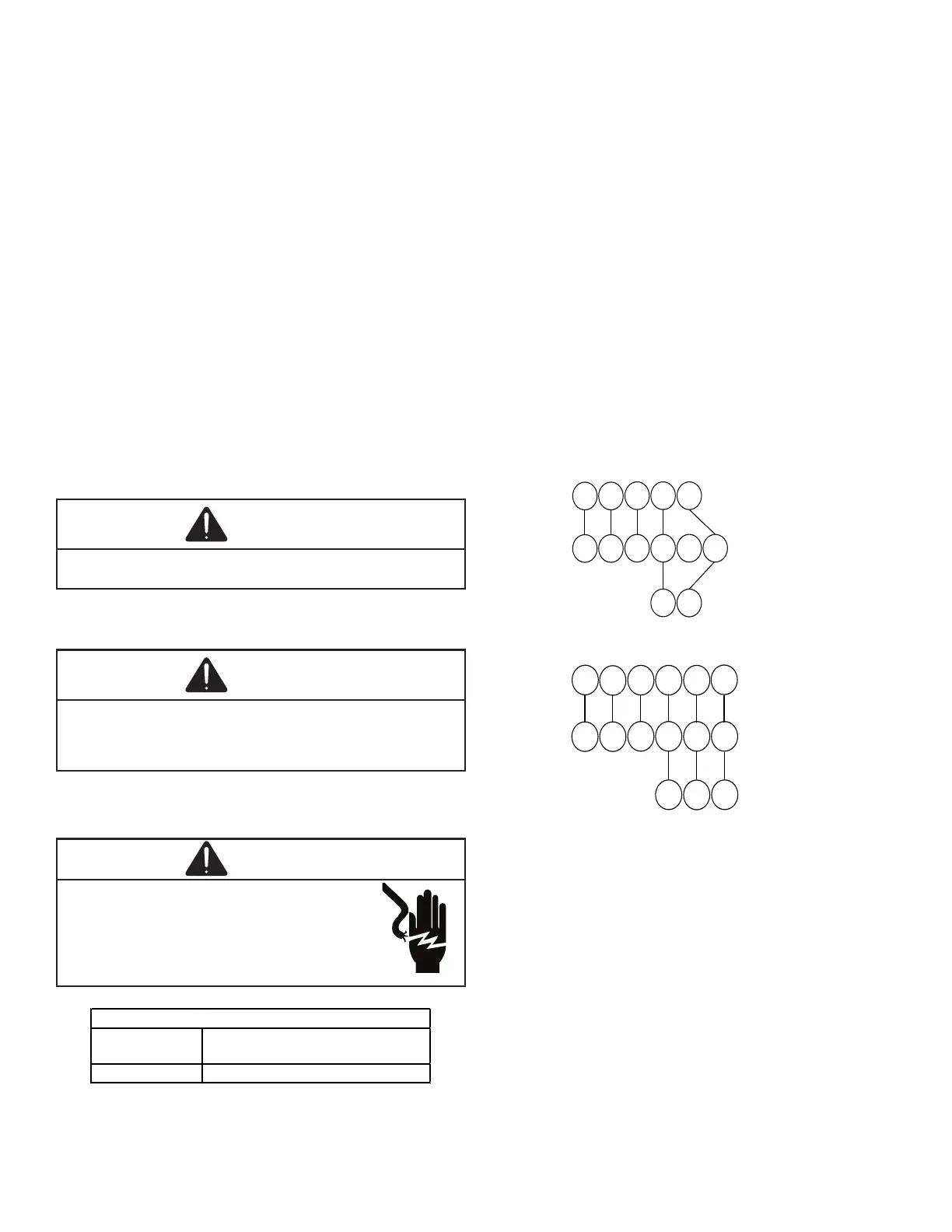
Thermostat - Single-Stage Heating with Single-Stage Cooling
Y1
C
Y1C
G
R
W
Y2
Y/Y1
C
G
R
W
ROOM THERMOSTAT
INTEGRATED FURNACE
CONTROL MODULE
REMOTE COOLING UNIT
(TWO STAGE)
Y2
Y2
Thermostat - Single-Stage Heating with Two-Stage Cooling
ξ˜©οŽ—οŽ›οŽ›οŽ‘οŽ”ξ˜ƒξ˜©οŽοŽοŽ”ξ˜ƒξ˜€οŽ˜οŽ˜οŽ”οŽ‘οŽ‹οŽ‰οŽœοŽ‘οŽ—οŽ–οŽ›
This furnace can be used in conjunction with a heat pump
in a fossil fuel application. A fossil fuel application refers to
a combined gas furnace and heat pump installation which
uses an outdoor temperature sensor to determine the most
ξ™†ξ™’ξ™–ξ™—ξ˜ƒξ™ˆσ°€©ξ™†ξ™Œξ™ˆξ™‘ξ™—ξ˜ƒξ™ξ™ˆξ™„ξ™‘ξ™–ξ˜ƒξ™’ξ™‰ξ˜ƒξ™‹ξ™ˆξ™„ξ™—ξ™Œξ™‘ξ™Šξ˜ƒξ˜‹ξ™‹ξ™ˆξ™„ξ™—ξ˜ƒξ™“ξ™˜ξ™ξ™“ξ˜ƒξ™’ξ™•ξ˜ƒξ™Šξ™„ξ™–ξ˜ƒξ™‰ξ™˜ξ™•ξ™‘ξ™„ξ™†ξ™ˆξ˜Œξ˜‘
A heat pump thermostat is required to properly use a sin-
gle-stage furnace in conjunction with a heat pump. Refer to
the fossil fuel kit installation instructions for additional ther-
mostat requirements.
Strictly follow the wiring guidelines in the fossil fuel kit instal-
lation instructions. All furnace connections must be made
to the furnace two-stage integrated control module and the
ξš³ξ˜©ξ˜Έξ˜΅ξ˜±ξ˜€ξ˜¦ξ˜¨ξš΄ξ˜ƒξ™—ξ™ˆξ™•ξ™ξ™Œξ™‘ξ™„ξ™ξ˜ƒξ™–ξ™—ξ™•ξ™Œξ™“ξ˜ƒξ™’ξ™‘ξ˜ƒξ™—ξ™‹ξ™ˆξ˜ƒξ™‰ξ™’ξ™–ξ™–ξ™Œξ™ξ˜ƒξ™‰ξ™˜ξ™ˆξ™ξ˜ƒξ™†ξ™’ξ™‘ξ™—ξ™•ξ™’ξ™ξ˜ƒξ™…ξ™’ξ™„ξ™•ξ™‡ξ˜‘ξ˜ƒ

Related product manuals