SYSTEM OPERATION
7
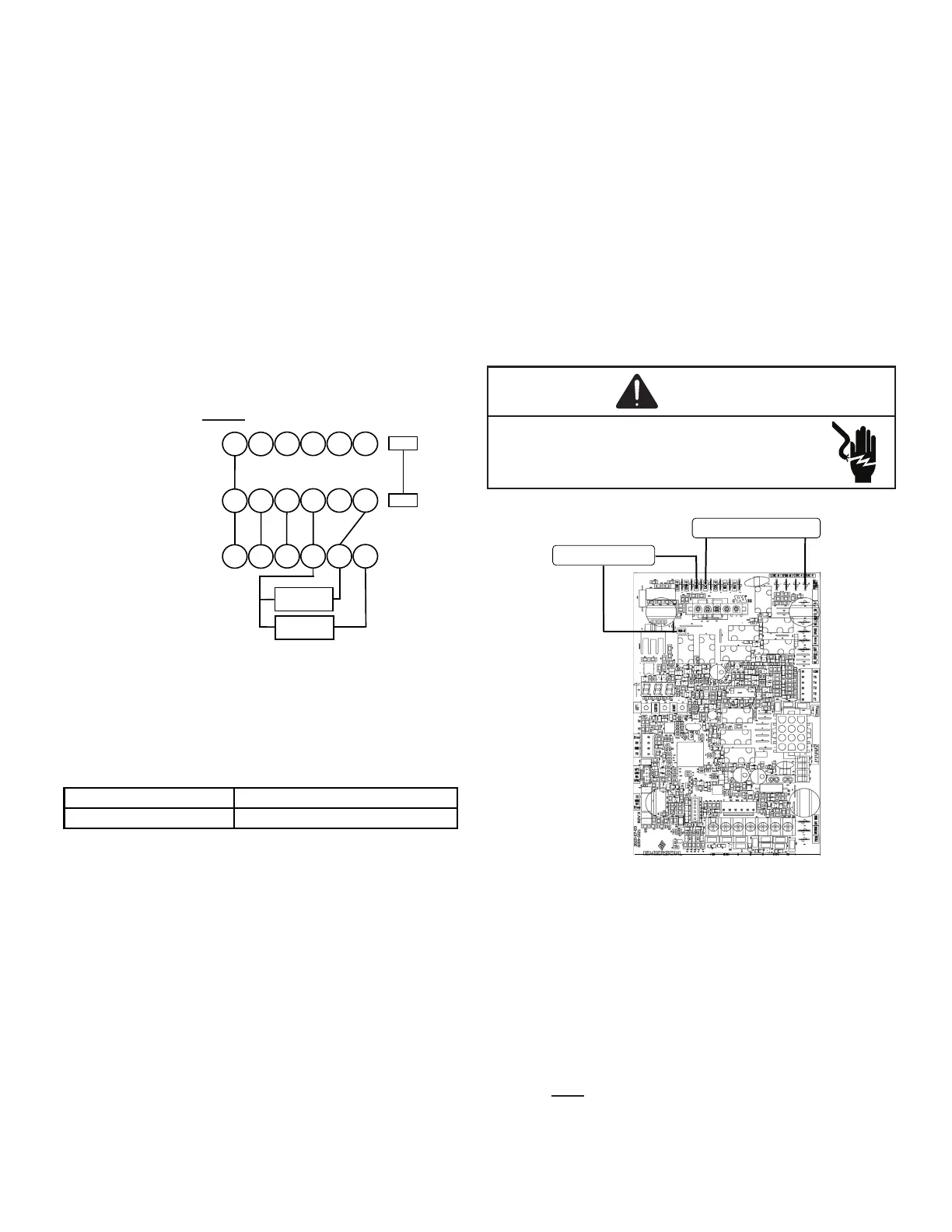
Two furnaces of the same model may be twinned. The in-
located beside the low voltage thermostat connection strip.
Twinning allows simultaneous operation of two furnaces and
forces the indoor blower motors of each furnace to operate
synchronously into a common duct system. Using the twin-
must be set the same on both furnaces.
Each furnace must be connected to it’s own 115
VAC power supply. The L1 connection to each furnace must
be in phase (connected to circuit breakers on the same 115
VAC service panel phase leg). To verify that the furnaces
are in phase, check from L1 to L1 on each furnace with a
voltmeter. If the furnaces are in phase, the voltage between
both furnaces will be ZERO.
ROOM THERMOSTAT
Y2
Y/Y1
C
G
R
W
Y2
Y/Y1
C
G
R
W
Y2
Y/Y1
C
G
R
W
TWIN
TWIN
COND UNIT
CONTACTOR
COND UNIT
CONTACTOR
FURNACE 1
FURNACE 2
The furnace integrated control module is equipped with line
voltage accessory terminals for controlling power to an op-
Turn OFF power to the furnace before installing any acces-
-
structions for locating, mounting, grounding, and controlling
these accessories. Accessory wiring connections are to be
conform to applicable codes. Connections should be made
as shown.
If it is necessary for the installer to supply additional line
voltage wiring to the inside of the furnace, the wiring must
conform to all local codes, and have a minimum temperature
rating of 105°C. All line voltage wire splices must be made
H) is energized with 115 volts whenever the induced draft
blower is energized. The integrated control module electron-
ic air cleaner terminal (EAC H) is energized with 115 volts
whenever the circulator blower is energized. This terminal
transformer. The remaining primary transformer wire would
be connected to the Line N on the control board.
-
115 VAC EAC
115 VAC HUM
W R G C Y
The furnace integrated control module is equipped with
a low voltage terminal for providing power to an optional
energized any time the draft inducer is powered. See con-
nection diagram below.
This is a 24 volt circuit only, the common connec-
tion must be on C terminal of the low voltage terminal strip
(where thermostat wires are connected). Wiring for this cir-
cuit must NOT be connected to the line N location where line
voltage neutral wires are connected.