EasyManua.ls Logo

Goodman GPG13 User Manual

Goodman GPG13
40 pages
To Next Page IconTo Next Page
Page #1 background imageLoading...
Page #1 background image
Affix this manual and Users Information Manual adjacent to the unit.
INSTALLATION & OPERATING
INSTRUCTIONS for
GPG13
SINGLE PACKAGE GAS-ELECTRIC
HEATING & COOLING UNIT
C
US
®
Goodman Manufacturing Company, L.P.
IO-288B 5151 San Felipe, Suite 500, Houston, TX 77056
07/08 www.goodmanmfg.com
© 2005 - 2008 Goodman Manufacturing Company, L.P.
*NOTE: Please contact your distributor or our
website for the applicable product data
book referred to in this manual.
This Forced Air Central Unit Design Complies With
Requirements Embodied in The American National
Standard / National Standard of Canada Shown Below.
ANSI Z21.47•CSA-2.3 Central Furnaces
RECOGNIZE THIS SYMBOL AS A SAFETY PRECAUTION.
ATTENTION INSTALLING PERSONNEL
Prior to installation, thoroughly familiarize yourself with this Installation Manual. Observe all safety warnings. During
installation or repair, caution is to be observed.
It is your responsibility to install the product safely and to educate the customer on its safe use.
These installation instructions cover the outdoor
installation of single package gas electric heating and
cooling units. See the Product Data Book applicable to
your model* for information regarding accessories.
Question and Answer IconNeed help?

Do you have a question about the Goodman GPG13 and is the answer not in the manual?

Goodman GPG13 Specifications

General IconGeneral
Cooling Capacity2 - 5 Tons
Compressor TypeSingle-Stage
RefrigerantR-410A
Fuel TypeNatural Gas or Propane
Vent TypeDirect Vent
Warranty10-Year Parts Limited Warranty (with registration)
StagesSingle-Stage
Thermostat CompatibilityStandard Thermostats
TypeGas Pack

Summary

Replacement Parts

Ordering Parts

Information on how to order replacement parts for the unit.

Safety Instructions

Crucial safety precautions for installers and owners.

Unit Location

Installation Locations

Requirements for all installations, ground level, and rooftop.

General Information

Rooftop and Curb Installation

Guidelines for rooftop installation and roof curb setup.

Transportation, Rigging, and Gas Piping

Transportation Damage Handling

Procedures for inspecting and claiming damages during transit.

Rigging Procedures

Instructions for safely lifting and moving the unit.

Gas Piping Requirements

Standards for gas supply piping installation and high altitude derate.

Gas Piping Checks and Propane Installation

Gas Piping Checks

Procedures for verifying gas piping integrity and connections.

Propane Gas Installation Details

Specific considerations for propane gas installations.

Tanks, Piping, Electrical, and Thermostats

Propane Gas Piping and Tanks

Information on tank sizing, regulators, and piping for propane.

Electrical Wiring Overview

General information regarding electrical wiring for the unit.

Thermostat Location Guidelines

Recommended placement for thermostats for optimal performance.

Electrical Connections and Settings

Unit Voltage Operation

Details on operating the unit at different voltages.

Heat Anticipator Setting

How to properly set the heat anticipator for heating cycles.

Airflow, Ductwork, and Filters

Airflow Conversion and Ductwork

How to convert airflow, install ductwork, and ensure proper air delivery.

Filter Requirements and Installation

Importance of filters and how to install them correctly.

Venting, Drains, and Operation Sequences

Flue Hood and Condensate Drain

Steps for flue hood installation and condensate drain connection.

Heating and Cooling Sequences

Step-by-step processes for heating and cooling operation.

Startup, Adjustments, and Checks

Heating Startup and Pre-Checks

Initial steps for heating startup and essential pre-operation checks.

Fan Only Operation

How the unit operates when only the fan is active.

Gas Pressure and Input Checks

Gas Inlet and Manifold Pressure

Procedures for checking and adjusting gas inlet and manifold pressures.

Gas Input Verification

Method to verify natural gas input rate.

Performance Checks and Blower Adjustments

Burner Flame and Temperature Rise

How to inspect burner flames and measure temperature rise.

Blower Speed Adjustments

How to adjust blower speed for optimal performance.

Unit Functions, Startup, and Troubleshooting

Dehumidification, Limit Checks, and Cooling Startup

Unit functions, limit checks, and cooling startup procedures.

Ignition Control Error Codes

Interpreting diagnostic LED flashes for error codes.

Abnormal Operation and Faults

Abnormal Heating and Cooling Operation

Causes and troubleshooting for heating and cooling faults.

Maintenance Procedures

Filter, Coil, and Motor Maintenance

How to maintain filters, outdoor coil, and motors.

Flame Sensor and Flue Passage Cleaning

Procedures for cleaning the flame sensor and flue passages.

Burner and Parts Information

Burner Flame Check and Cleaning

How to check and clean burner flames and burners.

Functional Parts List

List of major functional components of the unit.

Diagnostic Charts and Timing

Diagnostic Indicator Chart and Timing

Charts for diagnostic codes, heating, and cooling timing sequences.

Appendix

Unit Dimensions

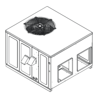
Visual representation of unit dimensions and port locations.

Wiring Diagrams

GPG13(24,30,36,42)1A Wiring Diagram

Electrical wiring diagram for GPG13 models 24, 30, 36, 42, 1A.

GPG13(48)1A Wiring Diagram

Electrical wiring diagram for GPG13 model 48, 1A.

GPG13(60)1A Wiring Diagram

Electrical wiring diagram for GPG13 model 60, 1A.

GPG13(36)3A Wiring Diagram

Electrical wiring diagram for GPG13 model 36, 3A.

GPG13(48,60)3A Wiring Diagram

Electrical wiring diagram for GPG13 models 48, 60, 3A.

GPG13(36)4A Wiring Diagram

Electrical wiring diagram for GPG13 model 36, 4A.

GPG13(48,60)4A Wiring Diagram

Electrical wiring diagram for GPG13 models 48, 60, 4A.

GPG13(48,60)1B Wiring Diagram

Electrical wiring diagram for GPG13 models 48, 60, 1B.

Clearances and Filters

Minimum Clearances Diagram

Visual guide showing required minimum clearances around the unit.

Recommended Filter Sizes

Table listing recommended filter sizes for different unit capacities.

Related product manuals