Do you have a question about the Goodman RS6200006 and is the answer not in the manual?
Explains safety symbols and general precautions for installation and operation.
High voltage, grounding, and approved device warnings to prevent shock and damage.
Warnings on technician qualifications, power supply, flammable materials, and CO hazards.
Instructions for inspecting the unit, verifying parts, and safe transport methods.
Compliance with codes, EPA regulations, and sourcing of replacement parts.
AHRI listing, system matches, refrigerant tubing, and clearance requirements.
Indoor installation, orientation options, and specific considerations for horizontal applications.
Details drip shield removal and drain connections for upflow and horizontal left configurations.
Explains the need for a downflow kit (DFK) and the conversion process for these orientations.
Warnings on pressure, handling, brazing, tubing size, and preparation for safe installation.
Specific instructions for flowrator piston adjustment and general notes for TXV models.
Step-by-step guide for connecting refrigerant lines on flowrator models, including purging and brazing.
Step-by-step guide for connecting refrigerant lines on TXV models, including pressure release and brazing.
Details on primary/secondary drain connections, fittings, torque, and insertion depth.
Covers secondary drains, traps, pump usage, and insulation for condensate lines.
Information on duct sizing, materials, and proper connection to the air handler.
Requirement for a return air filter, placement options, and filter types.
How airflow, voltage, and heat kit size determine temperature rise for heating mode.
Formula for estimating airflow and tables providing CFM data for various models.
Requirement for a cover plate when no electric heat kit is installed.
Inspection of building electrical service and verification of supply voltage agreement with unit requirements.
Guidelines for selecting wire size, using copper conductors, and installing maximum overcurrent protection.
Connecting supply voltage and heat kit power, including specific instructions for different heat kit types.
Connecting low voltage wiring for thermostats and condensers, including wire gauge and routing.
Instructions for changing blower motor speed by reconfiguring wire connections.
Steps to achieve less than 2% airflow leakage by ensuring gasket and panel integrity.
Comprehensive checklist for wiring, panels, tubing, drainage, and protection before unit start-up.
User's responsibility for filter maintenance; other services require a technician.
Tables providing airflow data (CFM) for ARUF/ARPT models across various static pressures and blower speeds.
Tables providing airflow data (CFM) for ASPT models across various static pressures and blower speeds.
Tables providing airflow data (CFM) for ASUF models across various static pressures and blower speeds.
Diagrams for cooling units with optional heat kits, showing thermostat and contactor connections.
Diagrams for heat pump units with optional heat kits, showing thermostat and outdoor thermostat connections.
Wiring diagrams for ARUF/ARPT heat pumps with optional heat kits, including outdoor thermostat options.
Wiring for ASPT/ASUF cooling units with heat kits, detailing thermostat and contactor connections.
Wiring for ASPT/ASUF heat pumps with heat kits, detailing thermostat and outdoor thermostat connections.
Wiring for ASPT/ASUF cooling units with 15kW+ heat kits, including outdoor thermostat options.
Wiring for ASPT/ASUF heat pumps with 10kW and below heat kits, showing thermostat and outdoor thermostat connections.
Detailed wiring for ASPT/ASUF heat pumps with 15kW+ heat kits, including outdoor thermostat options.
Diagram and explanation of the electronic blower time delay relay's function, timing, and field test mode.
Wiring schematics for ARUF/ARPT models with various heat kit configurations, including element rows.
Explanation of component codes, wiring codes, and important notes for ARUF/ARPT wiring.
Wiring schematics for ASPT/ASUF models with various heat kit configurations, including element rows.
Explanation of component codes, wiring codes, and important notes for ASPT/ASUF wiring.
Wiring diagram and notes for installing a 3-phase heat kit, including speed tap and label placement.
Wiring diagram and notes for installing a 25kW heat kit, including component and color codes.
Guidance on checking, cleaning, or replacing indoor air filters to maintain system efficiency and prevent damage.
Information that compressor and fan motors are sealed and permanently lubricated.
Recommendation for professional cleaning of the outdoor coil to ensure proper airflow and prevent damage.
Steps homeowners can take to check before calling a qualified servicer, such as thermostat settings and electrical panel.
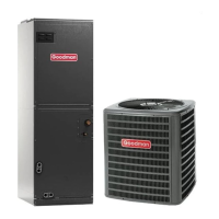
| Model | RS6200006 |
|---|---|
| Airflow | 2000 CFM |
| Refrigerant | R-410A |
| Phase | 1 |
| Cooling Capacity | 5 Ton |
| Heating Capacity | 60, 000 BTU/h |
| Voltage | 208/230V |
| Nominal Cooling Capacity | 5 Ton |
| Nominal Heating Capacity | 60, 000 BTU/h |