7 Technical Parameters & Block Diagram
7.1 Technical Parameters
~1 (Adjustable from 0.8 leading to 0.8 lagging)
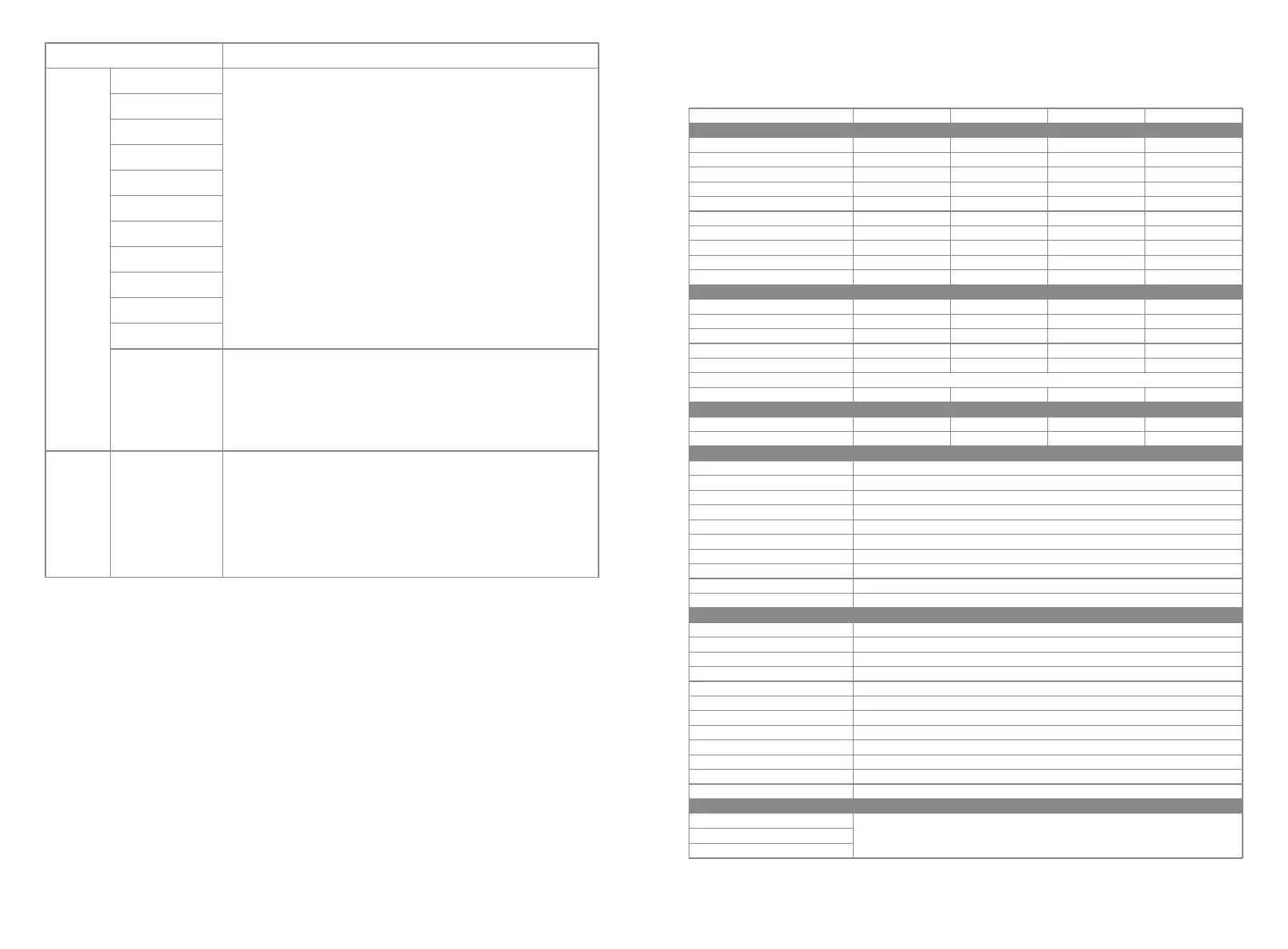
Technical Data
PV String Input Data
Max. DC Input Power (W)
Max. DC Input Voltage (V)
MPPT Range (V)
Start-up Voltage (V)
Min. Feed-in Voltage(V)
Nominal DC Input Voltage (V)
Max. Input Current (A)
Max. Short Current (A)
No. of MPP Trackers
No. of Input Strings per Tracker
AC Output Data
Nominal Output Power (W)
Max. Output Apparent Power (VA)
Nominal Output Voltage (V)
Nominal Ouput Frequency (Hz)
Max. Output Current (A)
Output Power Factor
Output THDi (@Nominal Output)
Efficiency
Max. Efficiency
Europe Efficiency
Protection
PV String Current Monitoring
Anti-islanding Protection
Input Reverse Polarity Protection
Insulation Resistor Detection
Residual Current Monitoring Unit
Output Over Current Protection
Output Short Protection
Output Over Voltage Protection
DC SPD Protection
AC SPD Protection
General Data
Operating Temperature Range (℃)
Relative Humidity
Operating Altitude (m)
Cooling
Noise (dB)
User Interface
Communication
Weight (kg)
Size (Width*Height*Depth mm)
Protection Degree
Night Self Consumption (W)
Topology
Certifications & Standards
Grid Regulation
Safety Regulation
EMC
Integrated
Integrated
Integrated
Integrated
Integrated
Integrated
Integrated
Integrated
Integrated(Type III)
Integrated(Type III)
-25~60
0~100%
≤4000
Natural Convection
<30
LCD & LED
RS485 or WiFi or LAN
24
516*415*192
IP65
<1
Transformerless
GW6000-DT
7800
1000
200~800
180
210
620
11/11
13.8/13.8
2
1/1
6000 [1]
6000
400, 3L/N/PE
50/60
10
<2%
98.0%
>97.5%
GW8000-DT
9600
1000
200~850
180
210
620
11/11
13.8/13.8
2
1/1
8000 [1]
8000
400, 3L/N/PE
50/60
12.1
<2%
98.3%
>98.0%
GW4000-DT
5200
1000
200~800
180
210
620
11/11
13.8/13.8
2
1/1
4000 [1]
4000
400, 3L/N/PE
50/60
8.5
<2%
98.0%
>97.5%
GW5000-DT
6500
1000
200~800
180
210
620
11/11
13.8/13.8
2
1/1
5000 [1]
5000
400, 3L/N/PE;
50/60
8.5
<2%
98.0%
>97.5%
Access main website to search the information
Note:
When sunlight is insufficient, the PV Inverter may continuously start up and shut down automati-
cally due to insufficient power generation by the PV panel.
1. Turn off DC switch of the inverter.
2. Wait till the inverter's LCD light is off.
3. Turn on DC switch and make sure it is connected.
4. If the problem still exists, contact local service office for help.
1. Turn off DC switch, take off DC connector, measure the voltage of PV array.
2. Plug in DC connector, and turn on DC switch.
3. If PV array voltage is lower than 250V , please check configuration of inverter
module.
4. If voltage is higher than 250V , please contact local office.
Type of fault Troubleshooting
Relay-Check Failure
DCI Injection High
EEPROM R/W Failure
SCI Failure
SPI Failure
DC BUS High
BUS Unbalance
GFCI Failure
Ifan Fault
Efan Fault
Afan Fault
No display
Wi-Fi module fail to
connect to network
Inverter
Failure
Others
1. If the Wi-Fi module fail to connect to network after choosing the right router
hotspot and entering the right passwords,it's possible that there are special
characters not supported by module in the hotspot passwords. Please modify
the password to consist of only Arabic numerals or uppercase / lowercase
letters.
2. If the problem still exists, contact local service office for help.
3029
 Loading...