DT/Smart DT (hereinafter referred to as SDT) series inverter of Jiangsu GOODWE Power Supply
Technology Co.,Ltd. ( hereinafter referred to as GOODWE ) strictly conforms to related safety rules
in design and test. As electric and electronic equipment, safety regulation shall be followed during
installation and maintenance. Improper operation may bring severe damage to the operator, the
third party and other properties. (DT: Dual-MPPT, Three-Phase, covering 12KWLV / 15KWLV / 12KW
/ 20KW / 25KW; SDT Smart Dual-MPPT, Three-Phase, covering 4KL / 5KL / 6KL / 10KL / 4KW / 5KW
/ 6KW / 8KW / 10KW / 15KW).
• Installation maintenance and connection of inverters must be performed by qualified personnel,
in compliance with local electrical standards regulations and the requirements of local power
authorities and or companies.
• To avoid electric shock, both AC output and DC input of the inverter must be disconnected for at
least 5 minutes before performing any installation or maintenance.
• The temperature of some parts of the inverter may exceed 60C during operation. To avoid being
burnt, do not touch the inverter during operation. Let it cool before touching it.
• Keep children away from the inverter.
• Without permission, opening the front cover of the inverter is not allowed. Users should not
touch/replace any of the components except for the DC/AC connectors. GOODWE will not bear
any consequences caused by unauthorized actions which will lead to potential injury to people
and damage to inverters.
• Static electricity may damage electronic components. Appropriate method must be adopted to
prevent such damage to the inverter; otherwise the inverter may be damaged and the warranty
will be annulled.
• Ensure the output voltage of the proposed PV array is lower than the maximum rated input
voltage of the inverter; otherwise the inverter may be damaged and the warranty will be
annulled.
• When exposed to sunlight, the PV array will generate very high voltage which will cause potential
danger to people. Please strictly follow the instruction we have provided.
• PV modules should have an IEC61730 class A rating.
• If the equipment is used in a manner not specified by the GOODWE, the protection provided by
the equipment's design may be impaired.
• To completely isolate the equipment : switch off the DC switch, disconnect the DC terminal, and
disconnect the AC terminal or AC breaker.
• Prohibit inserting or pulling the AC and DC terminals when the inverter is working.
• Only DC connectors provided by GOODWE are permitted for use, otherwise the inverter may be
damaged and the warranty will be annulled.
• Customers can access to inverter status through mobile phone and computer display please
refers to chapter 3.4.4 and 3.4.5. and error code could be shown not only on inverter LCD display
but also mobile phone App interface.
• The inverter can exclude the possibility of DC residual currents to 6mA in the system,Where an
external RCD is required in addition to the built-in RCMU, type A RCD must be used to avoid
tripping。
• The default photovoltaic module is not grounded.
• If there are more than 3 PV strings on input side, an additional fuse installation would be suggest-
ed.
To ensure IP64, inverters must be sealed well, please install the inverters within one day
after unpacking, otherwise please seal all used terminals/holes, any unused terminals /
holes are not allowed to be kept open, confirm that there is no risk of water or dust
entering terminals / holes.
To our inverter product, GOODWE provides standard manufacture warranty which comes with the
product and prepaid warranty extension solution to our customer. You can find the details about
the terms and solution from below linkage.
https://en.goodwe.com/warranty.asp
3 Product Introduction
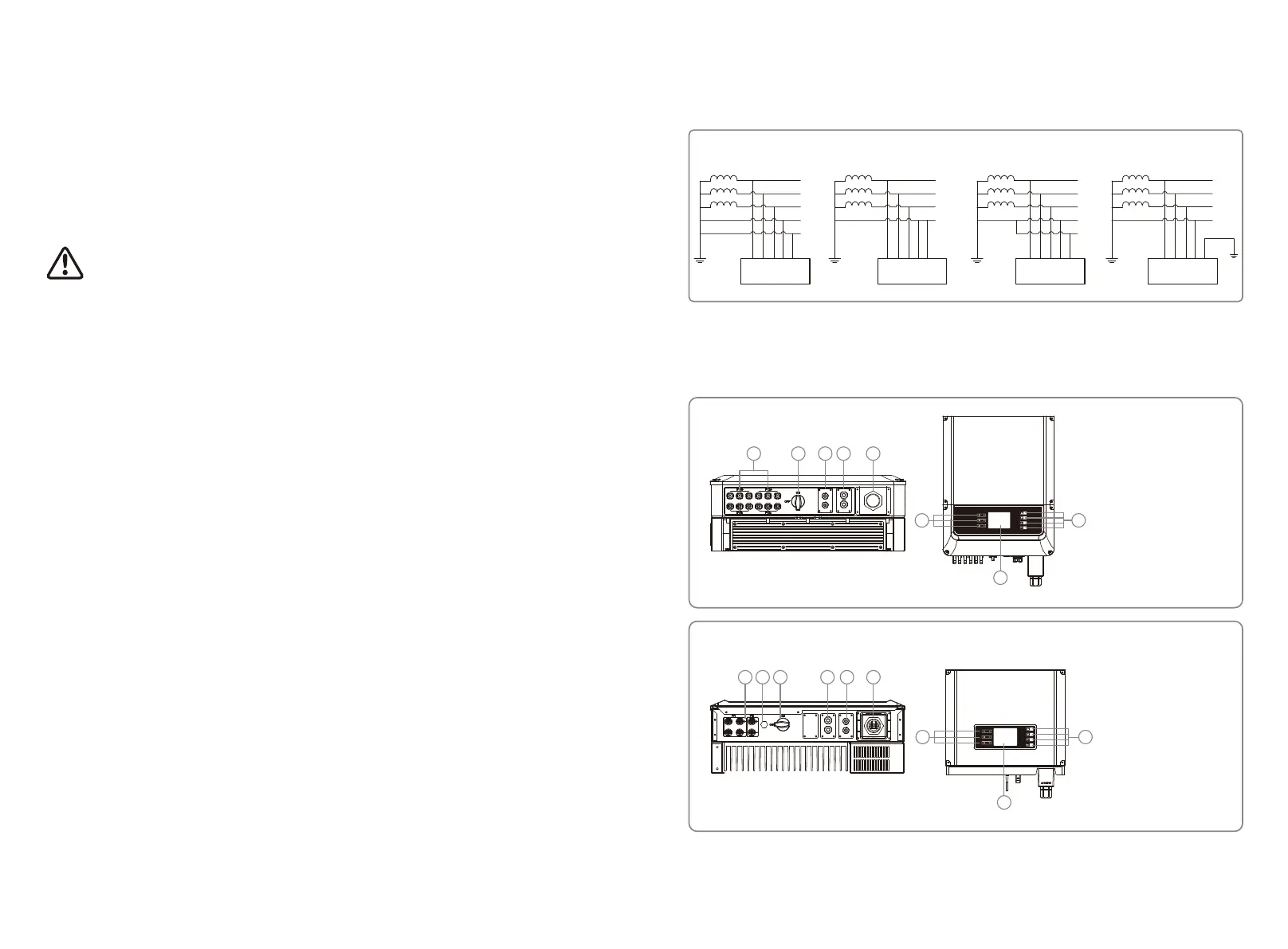
3.1 Grid Compatibility
DT series GW10KLV-DT ~ GW25K-DT and SDT series support four different types of grid.
3.2 Inverter Overview
TN-S TN-C TN-C-S
TT
L1
L2
L3
N
PE
PE
Transformer
Inverter
Transformer
L1
L2
L3
PEN
PE
Inverter
L1
L2
L3
N
PE
Transformer
PE
Inverter
L1
L2
L3
N
Transformer
PE
Inverter
Note: For TT grid structure, RMS voltage between neutral wire and earth wire must be less than
20V.
DT series
1. PV input Terminal
2. DC Switch (Optional)
3. CT & DRED / Remote
Shutdown Port (Optional)
4. RS485 / External WiFi
Module / USB Port
5. AC Output Terminal
6. Indicator Lights
7. LCD
8. Button
6
7
8
AC OUTPUT
CT/METER
DRED
RS485
RS485
1 2 3 4 5
SDT series
1. PV Input Terminal
2. Waterproof Vent
3. DC Switch (Optional)
4. RS485 Port / External WiFi
Module And USB Port
5. CT & DRED / Remote
Shutdown Port (Optional)
6. AC Output Terminal
7. Indicator Lights
8. LCD
9. Button
7
8
9
CT/METER
DRED
RS485
RS485
1 2 3 4 5 6
Note: The appearance of some SDT series inverters will be different.
0403
 Loading...