4.3 Electrical Connection
4.3.1 Connection To Grid (AC Side Connection)
1. Measure the voltage and frequency of grid-connected access point, and make sure it is in
accordance with the grid-connected standard of inverter.
2. It is recommended to add breaker or fuse to AC side. The specification should be more than 1.25
times of rated of AC output current.
3. The PE line of inverter should be connected to the earth, make sure that the impedance
between the neutral wire and earth wire is less than 10 ohm.
4. Disconnect the breaker or fuse between the inverter and the utility.
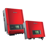
5. Connect the inverter to the grid as follows:
The wiring installation method on the AC output side is shown as below.
6. Fix (Torque:6~8 N.m) the connector of AC cable to the corresponding terminals.
7. Neutral conductor shall be blue, line conductor shall be black or brown (preferred), protective
earth bonding line shall be yellow-green.
8. The AC line construction shall be such that if the cord should slip from its anchorage, placing a
strain on conductors, the protective earthing conductor will be the last to take the strain. such
as the PE line is longer than L and N.
1. Timpose the line 2. Fasten screw cap clockwise 3. Ensure the wire be locked tightly
L1 ----- Live Wire 1
L2 ----- Live Wire 2
L3 ----- Live Wire 3
N ----- Neutral Wire
PE ----- Earth Wire
40~45mm
10~12mm
L1
L2 N
L3 PE
Cable specification of AC side .
Grade
A
B
C
D
Description
O.D.
Conductor Material Sectional Area
Wire Length
Bare Wire Length
Value
DT 15~25kW: 18~30mm; SDT 4~15kW: 11~23mm
DT 15~25kW: 4~25mm
2
; SDT 4~15kW: 4~10mm
2
45mm around
12mm around
Value of Conductor Material Sectional Area refer to the following table.
Model
GW12KLV-DT
GW15KLV-DT
GW15KN-DT
Conductor Material Sectional Area
6~10mm
2
10~25mm
2
4~10mm
2
Model
GW17K-DT
GW20K-DT
GW25K-DT
Conductor Material Sectional Area
4~10mm
2
6~10mm
2
10~25mm
2
Annealed copper wire
C D
A B
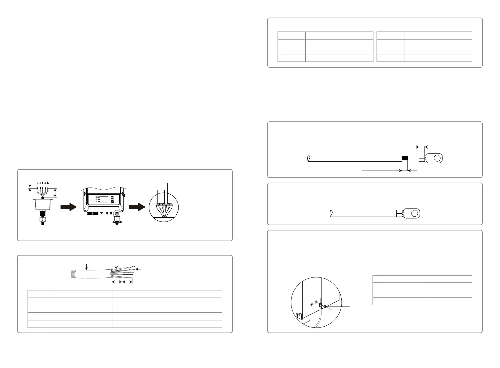
4.3.3 Earth Terminal Connection
The inverter is equipped with earth terminal according to the requirement of EN 50178.
All non-current carrying exposed metal parts of the equipment and other enclosures in the PV
power system must be grounded.
Please follow the steps below to connect "PE" cable to ground.
L1
L2 = L1 + (1~2mm)
Step 1
Strip the wire insulation sheet of a suitable length with a wire stripper.
A
B
C
NO.
A
B
C
Name
Cold-pressed terminal
Screw
Green & Yellow Cable
Explanation
M5*14
(1~1.5Nm)
4mm
2
/ 10AWG
Step 2
Insert the stripped wire into the terminal and compress it tightly by crimping pliers.
Step 3
Fix the earth wire on the machine.
In order to improve the corrosion resistance of the terminal, it is recommended to apply
silica gel on the earth terminal for corrosion protection after the grounding cable
assembly is completed.
1009
 Loading...