17
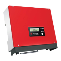
03 Product IntroductionUser Manual V1.1-2022-12-20
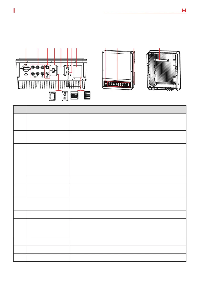
3.5 Appearance
3.5.1 Parts
No. Parts Description
1 DC Switch Starts or stops DC input.
Only for hybrid inverters.
GW5KL-ET, GW6KL-ET, GW8KL-ET,GW10KL-ET: optional.
2 PV input terminal Connects the PV module DC input cables.
Only for ET series and ET Plus series.
3 Battery input
terminal
Connects the battery input cables.
4 Communication
module port
Connects communication modules like Bluetooth, WiFi, LAN,
4G, etc.
Only for ET series and ET Plus series.
5 Communication port Supports RS485, DRED, RCR, DO, EMS etc.
6 Meter
communication port
Connects the smart meter communication cable.
7 BMS communication
port
Connects the battery BMS communication cable.
8 AC output terminal Connects the AC output cable.
9 Wi-Fi reset • Short press the button to restart the WiFi module.
• Long press for at least 3 seconds to factory reset the WiFi
module.
10 Indicators Indicates working status of the inverter.
11 PE terminal Connects the grounding cable.
12 Mounting Plate Used to install the inverter.
1 2 3 4 6 75
or
or
8
9
10 11 12
 Loading...