5.4.5 Menu Introduction
When PV panel is feeding power to the inverter, the screen shows the first interface of the
first-level menu. The interface displays current state of the system. It shows 'Waiting' when in the
initial state; it shows 'Normal' when in the power generation mode. If there is something wrong
with the system, an error message will be shown. Please refer to '5.6 Error Message'.
• In the first-llevel menu, the displayed information can be switched via the 'Up' and 'Down'
button operation. There are 6 interfaces in total, which are circulatory. The second-level menu
can only be selected using the 'Enter' button from the seventh interface.
• In the 'History Info' menu, press 'Enter' and 'Down' to select 'Error Log', press 'Enter' to enter
the historical error message interface. Press 'Up' and 'Down' to switch the display page and
inquire the historical error message. Press 'ESC' to return to the upper menu.
• In the 'Configuration' menu, select 'Date & Time' to enter the setting interface, Press 'Up' and
'Down' to change the data, short-press 'Enter' to move cursor, long-press 'Enter' to save the
settings.
• You must type in the password before entering the Advantage Setting. The inverter's default
password is 1111. You can set the parameters and modify the password after this password
verification is passed. If you forget your password, please contact after-sales for help.
• In 'Configuration' menu, select 'Language' and press 'Enter' to enter language setting interface,
press 'Up' or 'Down' to change language, long-press 'Enter' to save the settings, press 'ESC' to
return.
• In the 'History Info' menu, short-press 'Enter' to enter the second-level and third-level menu.
In the third-level menu, press 'up' or 'down' to inquire the historical power generation data in
Year Mode, Month Mode, Day Mode and Hour Mode. Press 'ESC' to return to upper menu.
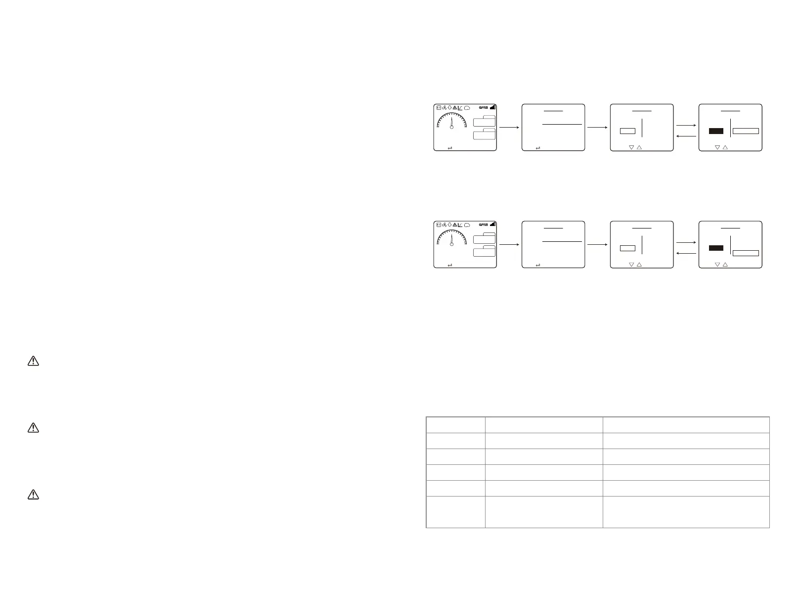
• In 'Configuration' menu, choose 'Comm' and press 'Enter' to enter the Modbus address
interface. Press 'Up' or 'Down' to set the address, long press 'Enter' to save the address.
This function is used for special requirements, please don't set it arbitrarily.
• In the second-level menu, select 'LVRT'(if LVRT mode has not been turned on), it will show
'[OFF]' on the right hand side of the LCD. Then press 'Up' or 'Down' to change the state to
'[ON]'. Long press 'Enter' to save the setting. Then the screen will soon display '[ON]' after a
while. This means that LVRT mode has been successfully turned on.
This function is used for special requirements, please do not set it arbitrarily.
• In the second-level menu, select 'Shadow'(if shadow mode has not been turned on). It will
show '[OFF]' on the right hand side of the LCD. Then press 'Up' or 'Down' to change the state to
'[ON]'. Long press 'Enter' to save the setting ,and the screen will display '[ON]' after a while, so
that the Shadow mode has been successfully turned on.
This function is used for special requirements, please do not set it arbitrarily.
• Select 'Safety' in the 'Configuration' menu, then press 'Enter', so that the set safety interface
will be shown. Press 'Down' or 'Up' to choose the safety you need and then long press 'Enter'.
The chosen safety option will be set. If there is no exact proper country code, please choose
'50Hz Grid Default' or '60Hz Grid Default' accordingly.
5.4 Wi-Fi Reset & Wi-Fi Reload
These functions are only available for Wi-Fi model inverters.
1. In the 'Configuration' menu, select 'Wi-Fi Reset' and press 'Enter' for 3 seconds to reset inverter
Wi-Fi module. Wait for a while. The operation result will be shown on the display. The function
can be applied when the inverter is unable to connect to router or monitor server.
Error code
01
02
03
07, 25
12
Error message
SPI Failure
EEPROM R/W Failure
Fac Failure
Relay Check Failure
LCD Communication Failure
Description
Internal communication failure
Memory chip failure
Grid Frequency exceed the inverter limit
Relay self-checking failure
Communication error occurs between
LCD DSP and the Master DSP
Enter
ESC
DownDown
Press ' '' ' to select menu
Configuration
Language
Date & Time
Comm
Safety
Modbus [001]
Substa [097]
WiFi Reset
WiFi Reload
Modbus [001]
Substa [097]
WiFi Reset
WiFi Reload
Press ' '' ' to change address
Configuration
Language
Date & Time
Comm
Safety
2. In the 'Configuration' menu, select 'Wi-Fi Reload' at lever 3. Press 'Enter' for 3 seconds. The
initial settings of the Wi-Fi module will be reloaded. Wait for a while. the operation result will be
shown on the display. The function can be applied when inverter is unable to connect to Wi-Fi
modulTe. After Wi-Fi modular is restored to its initial settings, the Wi-Fi module needs to be
reset again.
5.5 Precaution For Initial Startup
1. Make sure the AC circuit is connected and AC breaker is turned off.
2. Make sure the DC cable between inverter and PV string is connected, and the PV voltage is
normal.
3. Turn on the DC switch, and set safety according to the local regulation.
4. Turn on the AC breaker. Check the inverter work normal.
5.6 Error Message
The error message in below diagram will be displayed on the LCD if faults occur.
press ' ' to enter the setup interface
Running info
Grid volt
Grid curr
Grid Freq
DC volt 1~4
DC curr 1~4
Str curr 1~3
Str curr 4~6
Str curr 7~9
Str curr 10~13
999V
30.1A
10.1A
10.1A
10.1A
10.1A
999V
30.1A
10.1A
10.1A
10.1A
10.1A
999V
30.1A
10.1A
10.1A
10.1A
10.1A
999V
30.1A
10.1A
220.0V
95.6A
50.00Hz
220.0V
95.6A
50.00Hz
220.0V
95.6A
50.00Hz
press ' ' to enter the setup interface
80.00KW
Normal
999KWh
999KWh
19-07-18 11:37:20
E-day
Enter
ESC
DownDown
Press ' '' ' to select menu
Configuration
Language
Date & Time
Comm
Safety
Modbus [001]
Substa [097]
WiFi Reset
WiFi Reload
Modbus [001]
Substa [097]
WiFi Reset
WiFi Reload
Press ' '' ' to change address
Configuration
Language
Date & Time
Comm
Safety
press ' ' to enter the setup interface
Running info
Grid volt
Grid curr
Grid Freq
DC volt 1~4
DC curr 1~4
Str curr 1~3
Str curr 4~6
Str curr 7~9
Str curr 10~13
999V
30.1A
10.1A
10.1A
10.1A
10.1A
999V
30.1A
10.1A
10.1A
10.1A
10.1A
999V
30.1A
10.1A
10.1A
10.1A
10.1A
999V
30.1A
10.1A
220.0V
95.6A
50.00Hz
220.0V
95.6A
50.00Hz
220.0V
95.6A
50.00Hz
press ' ' to enter the setup interface
80.00KW
Normal
999KWh
999KWh
19-07-18 11:37:20
E-day
27 28
 Loading...