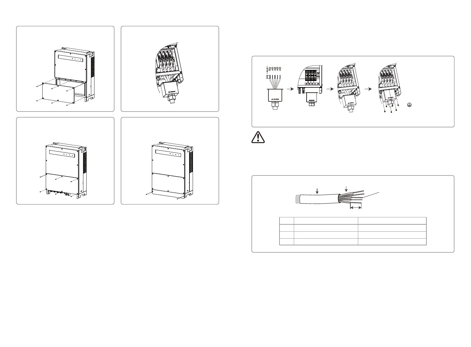
AC cable illustration :
7. Neutral conductor shall be blue; line conductor shall be black or brown (preferred); protective
earth bonding line shall be yellow-green.
8. The AC line construction shall be such that if the cord should slip from its anchorage, placing a
strain on conductors, the protective earthing conductor will be the last to take the strain.
Ensure the PE line is longer than L and N.
Connect the line to the terminal Tighten the nut Tighten the screws
L1 ----- Live Wire 1
L2 ----- Live Wire 2
L3 ----- Live Wire 3
N ----- Neutral Wire
----- Earth Wire
A
B
C
Value
30~38mm
25~95mm²
According to the terminal length
Grade
A
B
C
Description
O.D
Section area of conduction material
Length of bare wire
Annealed copper wire
4.3.2 AC Circuit Breaker and Residual Current Protection Device
An independent three or four pole circuit-breakers for each inverter must be installed at the
output side to ensure that the inverter can be safely disconnected from the grid.
The output current of GW30KLV-MT / GW50KN-MT is 80A. Thus we recommend that the nominal
current of the AC breaker be 100 A. The output current of GW35KLV-MT / GW50KBF-MT /
GW50KBF-MT-KR / GW60KN-MT / GW60KBF-MT / GW60KBF-MT-KR / GW70KHV-MT / GW80KHV-MT
and GW80KBF-MT is 90A. Thus, we recommend that the nominal current of the AC breaker be
120A.
Note: It is not necessary to connect Neutral wire to the inverter of GW30KLV-MT /
GW35KLV-MT / GW50KN-MT / GW60KN-MT / GW75K-MT / GW80K-MT products.
Please select Delta grid on the panel or SolarGo App, otherwise connect neutral
wire to them. Do not connect the neutral wire to the inverter of GW70KHV-MT,
GW80KHV-MT and GW80KBF-MT products.
L±3
L
4.2.3 Schematic of Cover Dismantling and Installation Steps
2. Electrical installation.1. Dismantle the downside cover.
(Tool: external hexagonal screwdriver)
3. Assemble bottom-side cover.
(Tool: hex button. Twisting Force: 2 N.m)
4. Assemble downside cover.
(Material: M5 inner-hexagon screws.
Tool: hex button)
4.3 Electrical Connection
4.3.1 Connection to Grid (AC Side Connection)
1. Measure the voltage and frequency of grid-connected access point, and ensure it is in
accordance with the grid-connected standard of the inverter.
2. It is recommended to add a breaker or fuse to the AC side. The specification should be more
than 1.25 times rating of the AC output current.
3. The PE line of the inverter should be connected to the earth, ensure that the impedance
between the neutral wire and earth wire is less than 10 Ω.
4. Disconnect the breaker or fuse between the inverter and the utility.
5. Connect the inverter to the grid. The wiring installation method on the AC output side is
shown as below:
6. Fix (Torque: 6-8 N.m) the connector of the AC cable to the corresponding terminals.
11 12
 Loading...