Caution
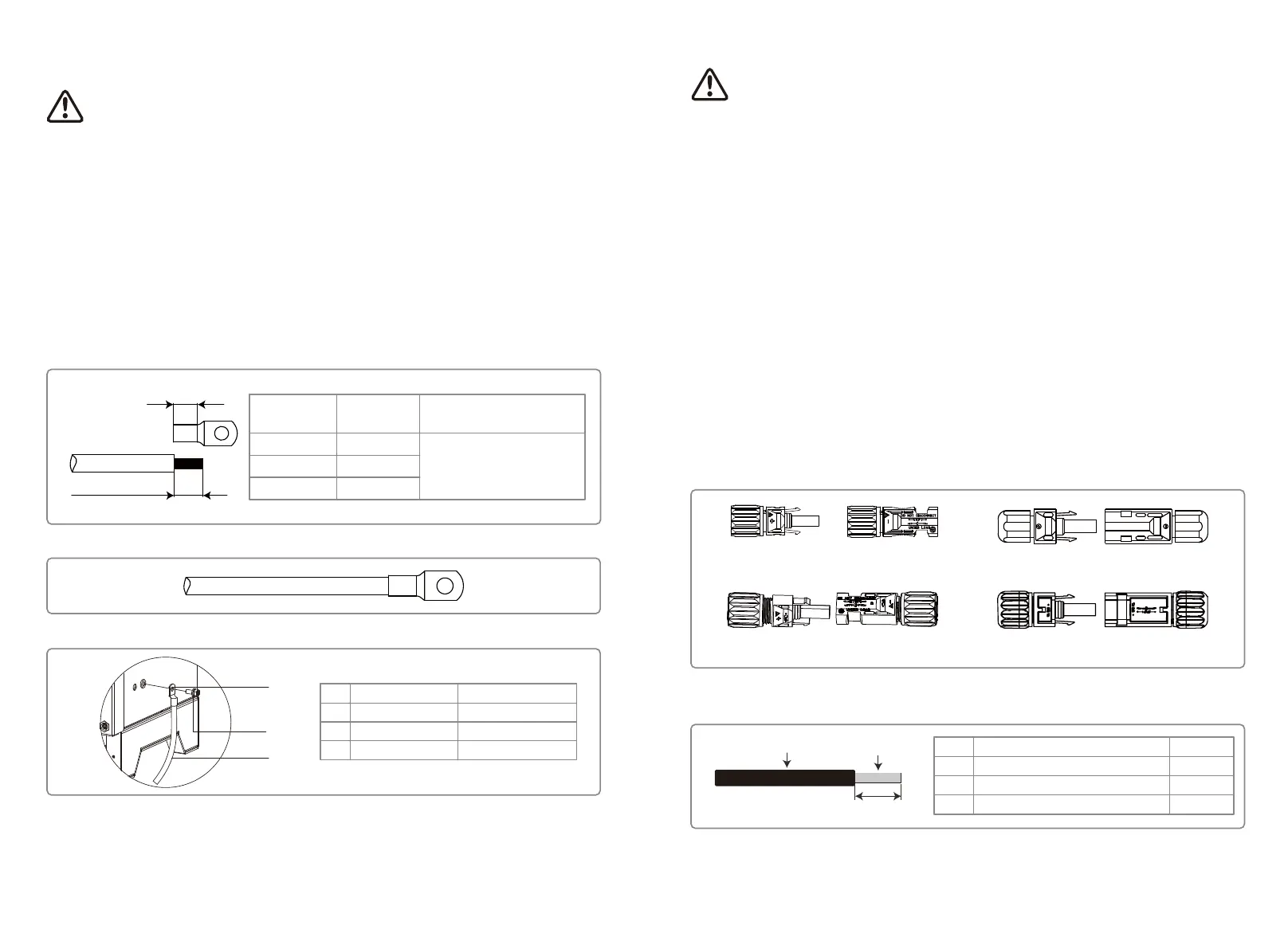
4.3.4 Connecting Inverter to PV Panel
DEVALAN SERIES MC4 SERIES
AMPHENOL SERIES QC4.10 SERIES
1. Ensure the DC switch is turned off before connecting PV string to the inverter.
2. Ensure PV string polarity confirms with DC connector. Otherwise, it will cause damage to invert-
er.
3. Ensure the maximum open circuit voltage (Voc) of each PV string does not exceed the maximum
input voltage of the inverter under any circumstances (1100V).
4. Ensure that the maximum short circuit current of each DC input is less than the inverter
allowable limit.
5. Do not connect positive or negative poles of PV string to earth (PE terminal). Otherwise, it will
destroy the inverter.
6. Positive cable should be red; negative cable should be black.
7. The minimum insulation resistance to ground of the PV panels must exceed 33.3kΩ (R = 1000/30
mA), there is a risk of shock hazard if the requirement of minimum resistance is not met.
8. The MT series has four PV input areas: PV1 input, PV2 input, PV3 input, PV4 input. Each has an
MPP tracker. The four PV inputs work independently. Therefore, the four PV inputs can be differ,
including different module types, numbers of connecting PV strings and orientation angels of
PV module.
There are four types of DC connectors: DEVALAN, MC4, AMPHENDL H4 and QC4.10 series.
Note: The actual DC connector used is as shown in the accessory box.
DC cable specification:
Value
4~5mm
2.5~4mm
2
About 7mm
Label
A
B
C
Description
External diameter of wire stock
Cross-sectional area of conductor material
Length of bare wire
A
B
C
The output current of GW50KLV-MT / GW50KLV-MT / GW80K-MT is 133A. Thus, we recommend
that the nominal current of the AC breaker should be more than 160A.
Note: It is not allowed for several inverter to use the same circuit breaker. Connecting loads
between the inverter and circuit breaker is also not allowed
The internal integrated residual current detection device (RCD) of the inverter can detect external
leakage-current in real time. When the detected leakage current value exceeds the limit value, the
inverter will be disconnected from the grid immediately. If an external RCD is installed, the action
current should be 500mA or higher.
4.3.3 Earth Terminal Connection
The inverter is equipped with an earth terminal, per the requirement of EN 50178.
All non-current carrying exposed metal parts of the equipment and other enclosures of the PV
power system must be grounded.
Please connect 'PE' cable to ground.
1. Strip the wire insulation sheet to a suitable length using a wire stripper, illustrated below.
4. To improve the corrosion resistance of the terminal, we recommended to applying silica gel to
the earth terminal for corrosion resistance after the grounding cable assembly is completed.
2. Insert the stripped wire into the terminal and compress it tightly by crimping pliers.
3. Fix the earth wire on the machine.
B
A
C
NO.
A
B
C
Name
Cold-pressed terminal
Screw
Yellow and green line
Explanation
M8*20
The maximum is 25mm
2
L1
L2=L1 + (1~2mm)
Section area of
PE cable
16mm²
16mm²
S/2
Note
Section area of
AC cable (S)
S > 16mm
2
S ≤ 35mm
2
S > 35mm
2
Only applicable when the material
of PE wire and L wire is the same.
If the material is different, please
select according to the equivalent
resistance of the PE wire.
13 14
 Loading...