GORAVE AR5 AUDIO RECEIVER
Owner’s Installation and Operation Manual
V1.4 / 12-16-2014
6
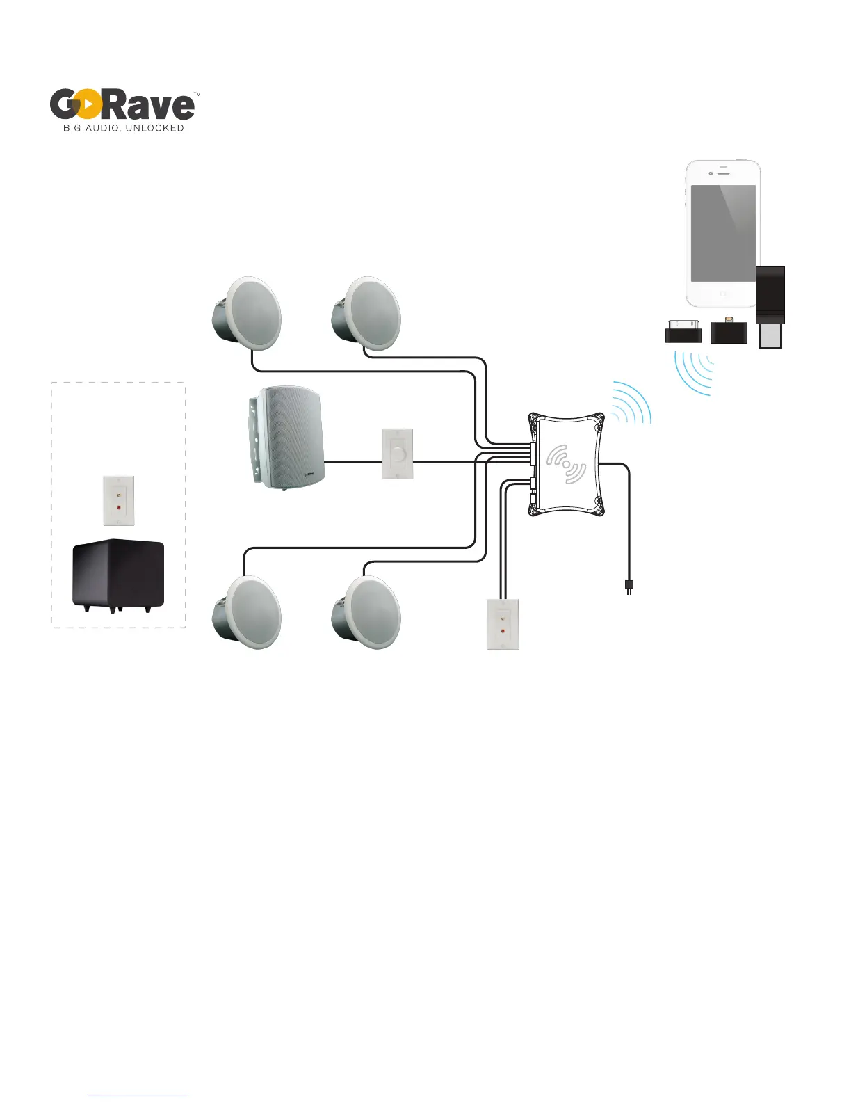
Push in a
GoRave Audio Sender
and press play
with any app
L
R
L
R
GoRave SC640W
ceiling speaker
GoRave HCRCA2W
wired auxiliary input
GoRave SC640W
ceiling speaker
GoRave SC640W
ceiling speaker
GoRave SC640W
ceiling speaker
GoRave SS650W
outdoor speaker
(blended stereo / mono)
GoRave CV35W
volume control
for outdoor
GoRave AR5
Audio Receiver
Subwoofer option:
Use blended/mono
output with banana plug
wall plate to connect
self-powered subwoofer
Sample wiring diagram (single zone) version 12/10/2013
AC power
connection
Fig 4: Sample wiring diagram showing a device transmitting audio from a GoRave Audio Sender to a GoRave AR5 Audio Receiver. In
this example, the AR5 amplies audio for two stereo speaker pairs (L + R) and one blended stereo (mono) weather-resistant outdoor
speaker.
Notice the AR5 is mounted vertically, with the output connectors on the left and the power connection on the right, for optimum wireless
reception.