5 - B.6.20.44-B
F22.060.03, issued on 01.98
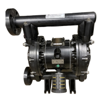
There must be a flexible connection between the reciprocating pump and the air pressure line
(avoids fractures caused by vibrations). A hose line is most suitable
- Nominal diameter 9 or larger
- Operational pressure = max. mains pressure, preferably ( 16 bar
- air and ambient temperatures -20° to +50 °C
- free from any substances that may interfere with paint spraying, such as silicone
In areas with a danger of explosion the air pressure line and the hose line must be electrically
conductive (to avoid electrostatic charging).
-
Discharge resistance < 10
6
Ω
relative to earth.
The pressure control valve is in most cases directly fitted to the reciprocating pump.
- Efficient flow rate
at 6 bar and 25m/s > 50 m3/h
- Air inlet pressure 16 bar
- Air and ambient temperatures 0° C to 50° C
It goes without saying that the pressure control valve can be situated between the hose line
and the air pressure line.
The manometer – 3.1 in functional diagram – enables accurate adjustment and monitoring of
the necessary air pressure.
- Display range 0 to 16 bar
- Air and ambient temperatures 0° to 50 °C
- Damped construction
A shut-off mechanism (e.g. a ball retaining valve) should always be fitted between the
pressure control valve and the hose line, or between the hose line and the air pressure line.
This enables quick and safe switch-off of the reciprocating pump for operational breaks,
maintenance work and in cases of breakdown.
- Do not change the values set on the pressure control valve
- Rated pressure ≥ 15 bar
- Material CuZn, nickel-plated
The rule for ball retaining valves: wings transverse to flow direction = line is closed off
Do not use PTFE tape or hemp to seal connections
(- malfunctioning of pressure control valve - as a result of residue in air pressure supply).