TYPICAL INSTALLATION
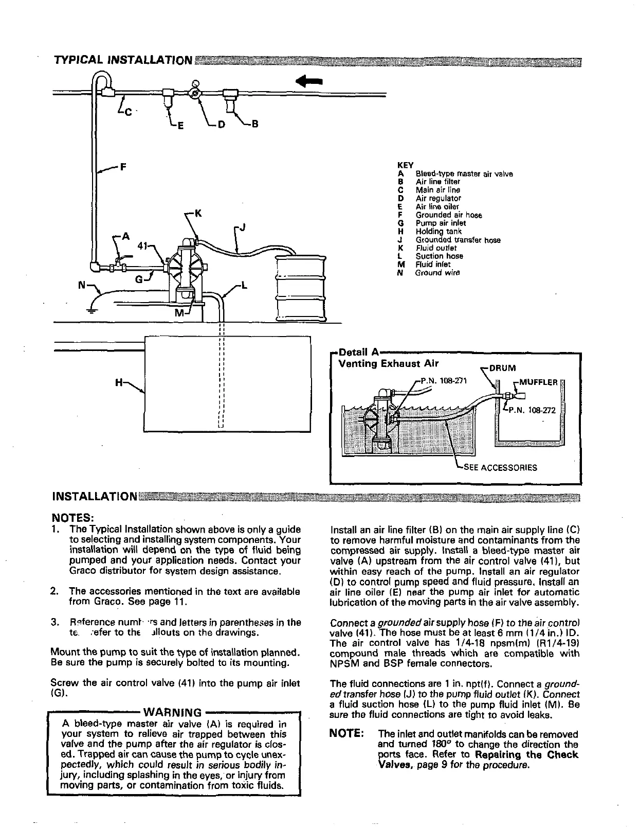
KEY
A
Bleed-type master air valve
B
Air line filter
C
Main
air
line
D
Air regulator
E
Air line oiler
F
Grounded air
hose
0
Pump
air
inlet
J
Grounded transfer
hose
H
Holding
tank
K
Fluid ourlet
L
Suction hose
N
Ground
wire
M
fluid inlet
Ir
Detail
A
Venting Exhaust
Air
I
LSEE
ACCESSORIES
INSTALLATION
NOTES:
1.
The Typical Installation shown above is only a guide
to selecting and installing system components. Your
installation
will
depend on the type of fluid being
pumped and your application needs. Contact your
Graco distributor for system design assistance.
2.
The accessories mentioned in the text are available
from Graco.
See
page 11.
3.
Roference numt.
'rs
and
letters
in
parentheses
in
the
tc. :efer to
the
Jllouts on the drawings.
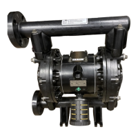
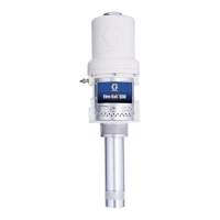
Mount
the
pump
to suit the
type
of installation planned.
Be sure the pump is securely bolted to its mounting.
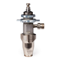
Screw the air control valve (41) into the pump air inlet
IG).
A
bleed-type master air valve
(A)
is
required in
WARNING
valve and the pump after the
air
regulator is clos-
your system to relieve air trapped between this
ed.
Trapped air can cause the pump
to
cycle unex-
pectedly, which could result
in
serious bodily
in-
jury, including splashing
in
the eyes;or injury from
moving parts, or contamination from toxic fluids.
to remove harmful moisture and contaminants from the
Install
an
air line filter
(BI
on the main air supply line
(C)
valve
(A)
upstream from the air control valve (411, but
compressed air supply. Install
a
bleed-type master air
within easy reach of the pump. Install
an
air regulator
(D)
to control pump speed and fluid pressure. Install an
air line oiler
(E)
near the pump air inlet for automatic
lubrication of the moving parts
in
the air valve assembly.
valve 141).
The hose must be at least
6
mm
(114
in.)
ID.
Connect a
grounded
air supply
hose
IF)
to the air control
The air control valve has 1/4-18 npsm(m) (R1/4-19)
compound male threads which are compatible with
NPSM
and
BSP
female connectors.
The fluid connections are 1
in.
npt(f). Connect a ground-
ed transfer
hose
IJ)
to
the
pump
fluid outlet
(K).
Connect
a fluid suction hose
(L)
to the pump fluid inlet
(MI.
Be
sure the fluid connections are tight to avoid leaks.
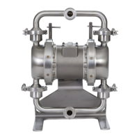
NOTE:
The inlet and outlet manifolds can be removed
and turned
180°
to
change the direction the
pons
face. Refer to Repairing
the
Check
Valves,
page
9
for the procedure.