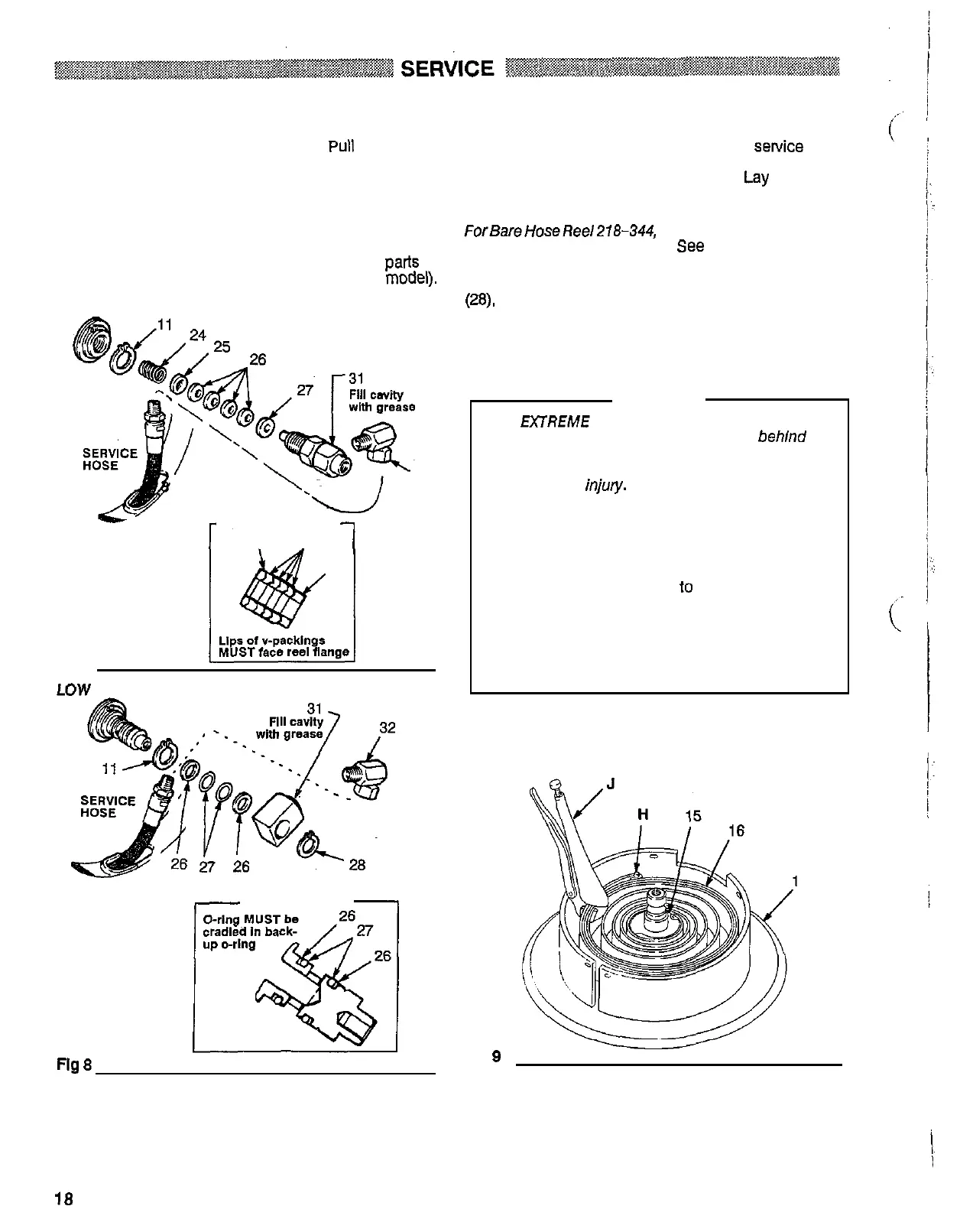
Swivel
Shut
off
the air or
fluid
supply. Open the dispensing valve
to
relieve pressure fromthe service hose. Pull the hose
Out
fully and engage the latch.
Disassemble the parts as shown in Figures
7
and
8
(depending on your hose reel model). Clean the parts and
inspect them for wear or damage.
Grease the new parts, and fill the cavity of the swivel
assembly (31) with high
-
quality grease. Install the parts as
shown
in
Fig
7
or
8
(depending on your hose reel model).
HIGH PRESSURE BARE REEL 218
-
344
32
r
REEL
FLANGE
-u
-
PACKING DETAIL
7
25 26
27
Fig
7
LOW PRESSURE BARE REEL 218
-
345
REEL
FLANGE
I
PACKING DETAIL
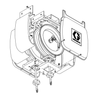
Reel
Spring
Shut
off
the air or water supply to the reel. Open the dis
-
pensing valve to relieve pressure from the Sewice hose.
Remove the service hose as described on page 15.
Remove the reel from its mounting base.
Lay the reel on
a flat surface
so
the pedestal
(1)
is on the bottom.
ForBareHoseReel218-344, removetheswivelassembly
(31) and the retaining ring
(1
1).
See
Fig
7.
For
Bare
Hose
Reel
218
-
345, remove the retaining ring
(28),
swivel (31) and retaining ring (1 1). See Fig
8.
Remove the screws (1
8)
and nuts (20) from the reel flanges
(13 and 17). Refer
to
the parts drawings, pages 18 or 20.
WARNING
USE MTREME CAUTION WHEN HANDLING THE
flange, isundergreattensionandcouldbepropelled
SPRING!
The
spring,
which
is
located behlnd the
from
the lower flange
(13)
with enough force to cause
serious bodily
iniory.
To
reduce the risk of serious bodily injury,
use
extreme caution when removing the top reel flange
(17).
Be
sure the reel is laying flat, and then carefully
lifl
up on the flange to expose the spring
(16).
ALWAYS
use
locking pliers
to
compress and hold
several rows of the spring together when removing
and when installing a spring.
See
Fig
9.
Before disposing of the
spring,
carefully attach a
minimum of
two
hose clamps around the keeper and
spring bands as shown in Fig 10.
3 3
Fig
8
Flg
9
-
18
307
-
694
 Loading...