Installation
For For
For
Fluid Fluid
Fluid
Control Control
Control
Systems Systems
Systems
with with
with
Atomizing Atomizing
Atomizing
Air Air
Air
or or
or
Fluid Fluid
Fluid
Pressure Pressure
Pressure
Operation Operation
Operation
Capability Capability
Capability
above above
above
50 50
50
psi psi
psi
(3.5 (3.5
(3.5
bar) bar)
bar)
Key: Key:
Key:
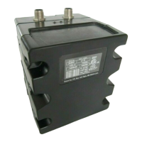
A A
A
PowerSupply(seeProControl1KEPlus
SelectionGuide,page6,foralternatepower
supplymoduleoptions)
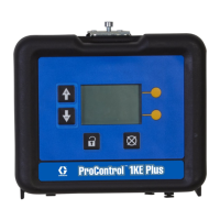
B B
B
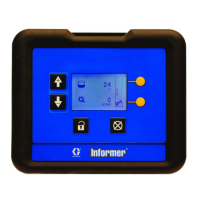
ProControl1KEPlusADCM
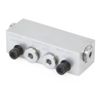
C C
C
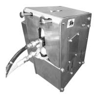
FluidPanel
L L
L
2–WayVentedValve
M* M*
M*
AirSupplyLine
N* N*
N*
AirOutletLinetoGun
P* P*
P*
FluidOutletLine
Key: Key:
Key:
R* R*
R*
FluidInletLine
S* S*
S*
FluidInletShut-offValve
U U
U
GroundWire
V* V*
V*
Gun
AE AE
AE
Powercables,availableforusewith
additionalProControl1KEPlusunits(see
ProControl1KEPlusSelectionGuide,page
6
* *
*
User-provided.
22
3A6948A
 Loading...