Installation
Air Air
Air
Connections Connections
Connections
Connectincomingairsupplytotheairsupplyshut-off
valve(L)1/4npt(f).(SeeComponents,page17.)
NOTICE NOTICE
NOTICE
ToavoiddamagetotheI/Ptransducer,useclean,
dry,oil-freeair,lteredthroughatleasta40micron
lter.
SeeTechnicalSpecications,page88,forair
pressureandconsumptionratings.TheI/P
transducerexhaustsasmallamountofairwhenever
airisconnected,regardlessofwhetherthesystemis
operating.Refertoyourapplicatorgunairpressure
andconsumptionratingsandsizeyourairsupply
accordingly.
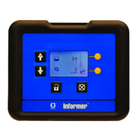
TheProControl1KEPlususesanAirFlowSwitch
(AFS)todetectwhentheapplicatorgunistriggered.
DonotbypasstheAFS.SeeAccessories,page77,
foranalternateguntriggerairpressureswitchthat
canbeusedinplaceoftheprovidedAFS.
NOTE: NOTE:
NOTE:
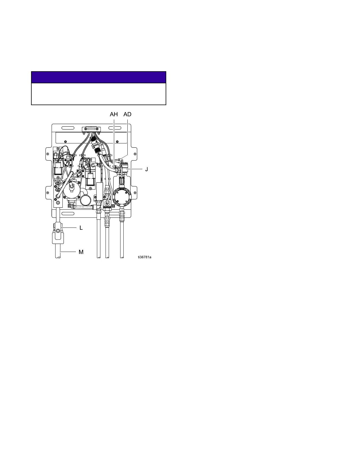
•Thesideport(AH)ontheuidregulator
canbeusedforhigh-speedushingwithan
independentairsource.Settheairpressure
higher higher
higher
thanthetopport(AD)airpressure.See
SetupScreen11:FillMode,page51,and
SetupScreen12:FlushMode,page52,for
thepreferredmethodofcontrollingllandush
pressure.
•Flushingairpressuremustberemovedfromthe
sideport(AH)toreturntothepreviousowsetting.
24
3A6948A
 Loading...