Instructions
DCM DCM
DCM
and and
and
ADCM ADCM
ADCM
332013E
EN
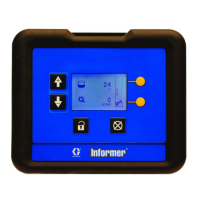
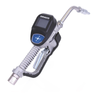
Display Display
Display
Control Control
Control
Module Module
Module
(DCM) (DCM)
(DCM)
and and
and
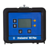
Advanced Advanced
Advanced
Display Display
Display
Control Control
Control
Module Module
Module
(ADCM), (ADCM),
(ADCM),
used used
used
to to
to
monitor monitor
monitor
and and
and
control control
control
ow ow
ow
rate rate
rate
and and
and
track track
track
material material
material
use. use.
use.
For For
For
professional professional
professional
use use
use
only. only.
only.
Important Important
Important
Safety Safety
Safety
Instructions Instructions
Instructions
Readallwarningsandinstructionsinthismanual.Save Save
Save
these these
these
instructions. instructions.
instructions.
See See
See
page page
page
3 3
3
for for
for
kit kit
kit
information, information,
information,
including including
including
approvals. approvals.
approvals.
PROVENQUALITY.LEADINGTECHNOLOGY.