308441 17
Service
Diaphragm Repair
Tools Required
Torque wrench
13 mm socket wrench
15 mm socket wrench (aluminum models) or
1 in. socket wrench (stainless steel models)
19 mm open–end wrench
O-ring pick
Lithium-base grease
Disassembly
NOTE: A Fluid Section Repair Kit is available. Refer to
page 23 to order the correct kit for your pump. Parts
included in the kit are marked with an asterisk, for
example (401*). Use all the parts in the kit for the best
results.
WARNING
To reduce the risk of serious injury whenever you
are instructed to relieve pressure, always follow the
Pressure Relief Procedure on page 9.
1. Relieve the pressure.
2. Remove the manifolds and disassemble the ball
check valves as explained on page 16.
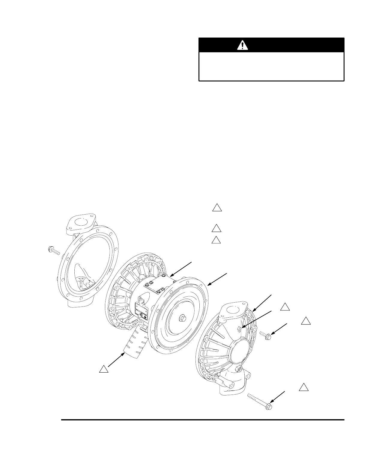
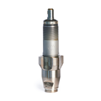
3. Using a 13 mm socket wrench, remove the screws
(106 and 112) holding the fluid covers (101) to the
air covers (23). Pull the fluid covers (101) off the
pump. See Fig. 11.
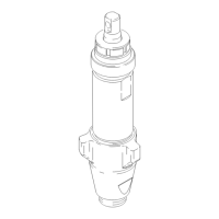
Fig. 11
1
2
23
101
A
2
B
Arrow (A) must point toward air valve (B).
Apply medium-strength (blue) Loctite or equivalent to
the threads. Torque to 190–220 in-lb (22–25 Nm).
See Torque Sequence, page 28.
1
106
112
1
03273C
3
Muffler not included on Model No. 253485.
3